

Arduino 上手教程
2. 设备开发 & 案例程序
3. M5Unified
4. M5GFX
5. 扩展模块
Unit
Module
Atomic
Tab5
IoT
Module13.2 4Relay v1.1 Arduino 使用教程
1. 准备工作
- 环境配置:参考 Arduino IDE 上手教程 完成 IDE 安装,并根据实际使用的主控安装对应的板管理与驱动。
- 使用到的驱动库:
- 使用到的硬件产品:

2. 注意事项
负载与接线
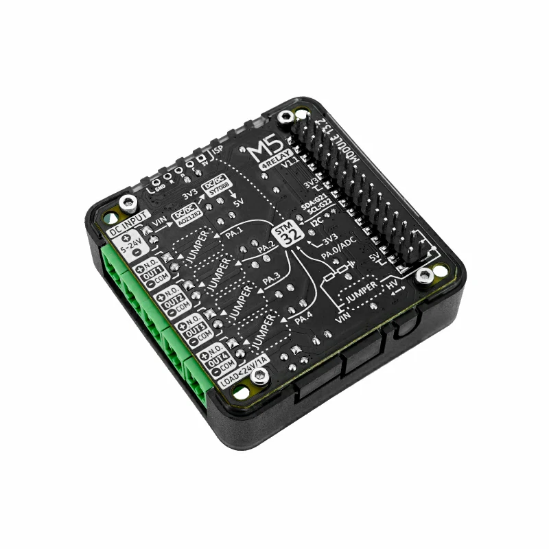
Module13.2 4Relay v1.1 仅支持直流线路通断,产品标注 4 通道最大负载能力为 24W (DC 24V@1A)。继电器端子为
COM 和 NO,请根据实际负载和电源规格接线。接线、拆线或更换负载前必须断开电源。工作模式
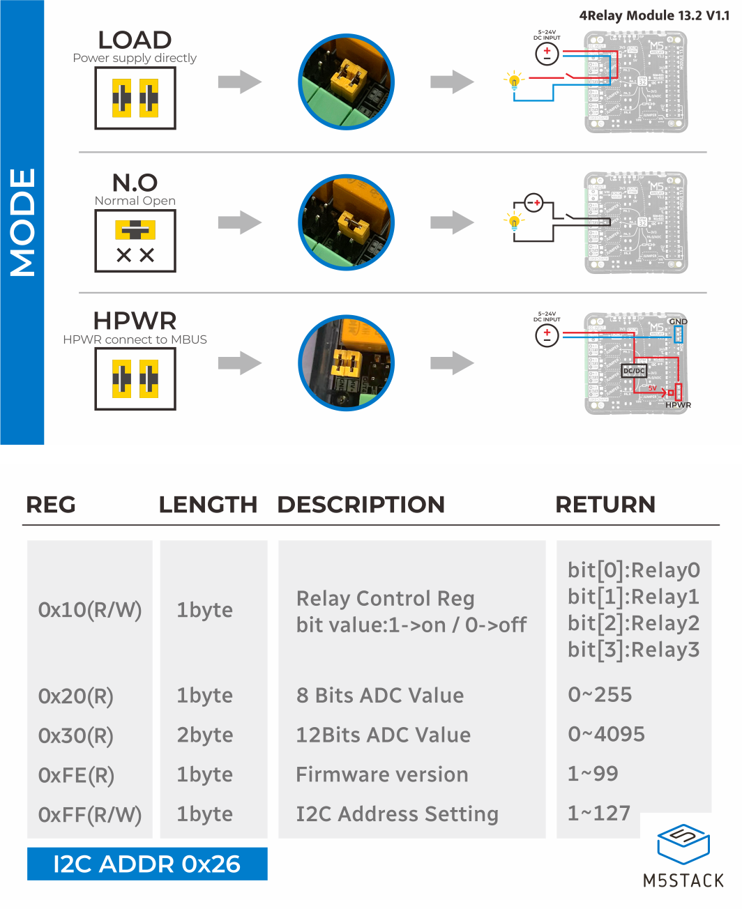
请根据产品接线说明书安装跳线帽,选择有源或无源工作模式。使用外部 DC 5 ~ 24V 电源时,请确认电源极性和负载电压符合产品规格;不要将交流电接入本模块。
引脚兼容性
由于每款主控的 I2C 引脚配置不同,使用前请参考产品文档中的引脚兼容表,并根据实际连接修改案例程序。
3. 案例程序
本教程使用 CoreS3 搭配 Module13.2 4Relay v1.1。模块通过 I2C 通信,默认地址为 0x26,CoreS3 连接后的 I2C 引脚为 G12 (SDA) 和 G11 (SCL)。程序使用 CoreS3 触摸屏控制继电器:点击 STEP 切换当前通道,点击 ALL ON 打开全部通道,点击 ALL OFF 关闭全部通道。
cpp
1 2 3 4 5 6 7 8 9 10 11 12 13 14 15 16 17 18 19 20 21 22 23 24 25 26 27 28 29 30 31 32 33 34 35 36 37 38 39 40 41 42 43 44 45 46 47 48 49 50 51 52 53 54 55 56 57 58 59 60 61 62 63 64 65 66 67 68 69 70 71 72 73 74 75 76 77 78 79 80 81 82 83 84 85 86 87 88 89 90 91 92 93 94 95 96 97 98 99 100 101 102 103 104 105 106 107 108 109 110 111 112 113 114 115 116 117 118 119 120 121 122 123 124 125 126 127
#include <M5Unified.h>
#include "Module_4RELAY.h"

MODULE_4RELAY relay;
TwoWire *relayWire = &Wire1;

uint8_t currentChannel = 0;

constexpr uint8_t RELAY_SDA = 12;
constexpr uint8_t RELAY_SCL = 11;
constexpr int16_t TOUCH_BUTTON_Y = 176;
constexpr int16_t TOUCH_BUTTON_HEIGHT = 58;
constexpr int16_t TOUCH_BUTTON_WIDTH = 100;
constexpr int16_t TOUCH_BUTTON_GAP = 6;

int16_t getButtonX(uint8_t index)
{
    return TOUCH_BUTTON_GAP + index * (TOUCH_BUTTON_WIDTH + TOUCH_BUTTON_GAP);
}

int8_t getTouchedButton(int16_t x, int16_t y)
{
    if (y < TOUCH_BUTTON_Y || y >= TOUCH_BUTTON_Y + TOUCH_BUTTON_HEIGHT) {
        return -1;
    }

    for (uint8_t index = 0; index < 3; ++index) {
        const int16_t buttonX = getButtonX(index);
        if (x >= buttonX && x < buttonX + TOUCH_BUTTON_WIDTH) {
            return index;
        }
    }
    return -1;
}

void drawTouchButton(uint8_t index, const char *label)
{
    const int16_t x = getButtonX(index);
    M5.Display.fillRoundRect(x, TOUCH_BUTTON_Y, TOUCH_BUTTON_WIDTH,
                             TOUCH_BUTTON_HEIGHT, 5, TFT_DARKGREY);
    M5.Display.drawRoundRect(x, TOUCH_BUTTON_Y, TOUCH_BUTTON_WIDTH,
                             TOUCH_BUTTON_HEIGHT, 5, TFT_ORANGE);
    M5.Display.setTextDatum(MC_DATUM);
    M5.Display.setTextColor(TFT_WHITE, TFT_DARKGREY);
    M5.Display.drawString(label, x + TOUCH_BUTTON_WIDTH / 2,
                          TOUCH_BUTTON_Y + TOUCH_BUTTON_HEIGHT / 2);
}

void showStatus(const char *action)
{
    const uint8_t state = relay.getAllRelayState();

    M5.Display.fillScreen(TFT_BLACK);
    M5.Display.setTextColor(TFT_WHITE, TFT_BLACK);
    M5.Display.setTextSize(2);
    M5.Display.setTextDatum(TL_DATUM);
    M5.Display.drawString("Module13.2 4Relay", 8, 8);
    M5.Display.drawString(action, 8, 32);

    for (uint8_t index = 0; index < 4; ++index) {
        const bool isOn = (state >> index) & 0x01;
        M5.Display.setCursor(8, 60 + index * 26);
        M5.Display.printf("CH%u: %s%s", index + 1, isOn ? "ON" : "OFF",
                          index == currentChannel ? "  <" : "");
    }

    Serial.printf("%s | relay state: 0x%02X\n", action, state);
    drawTouchButton(0, "STEP");
    drawTouchButton(1, "ALL ON");
    drawTouchButton(2, "ALL OFF");
}

void setup()
{
    M5.begin();
    Serial.begin(115200);

    while (!relay.begin(relayWire, MODULE_4RELAY_ADDR, RELAY_SDA, RELAY_SCL,
                        200000L)) {
        Serial.println("4RELAY INIT ERROR");
        M5.Display.fillScreen(TFT_BLACK);
        M5.Display.setTextColor(TFT_RED, TFT_BLACK);
        M5.Display.setTextSize(2);
        M5.Display.setTextDatum(TL_DATUM);
        M5.Display.drawString("4RELAY INIT ERROR", 8, 8);
        delay(1000);
    }

    Serial.println("4RELAY INIT SUCCESS");
    relay.setAllRelay(false);
    showStatus("Ready");
}

void loop()
{
    M5.update();

    const auto touch = M5.Touch.getDetail();
    if (touch.wasClicked()) {
        switch (getTouchedButton(touch.x, touch.y)) {
        case 0: {
            const bool nextState = !relay.getRelayState(currentChannel);
            const bool success = relay.setRelay(currentChannel, nextState);
            currentChannel = (currentChannel + 1) % 4;
            showStatus(success ? "Channel updated" : "Channel update error");
            break;
        }

        case 1: {
            const bool success = relay.setAllRelay(true);
            showStatus(success ? "All ON" : "All ON error");
            break;
        }

        case 2: {
            const bool success = relay.setAllRelay(false);
            showStatus(success ? "All OFF" : "All OFF error");
            break;
        }

        default:
            break;
        }
    }

    delay(20);
}4. 编译上传
- 1. 进入下载模式:CoreS3 长按复位按键 (大约 2 秒) 直到内部绿色 LED 灯亮起后松开按键。松开后绿色 LED 灯熄灭,表示设备已进入下载模式,等待烧录。
说明
不同设备进行程序烧录前需要进入下载模式,不同的主控设备该步骤可能有所不同。详情可参考Arduino IDE上手教程页面底部的设备程序下载教程列表,查看具体的操作方式。
.gif)
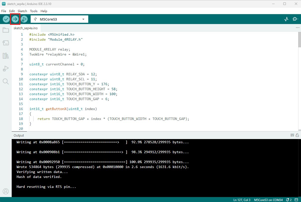
- 2. 选中设备端口,点击 Arduino IDE 左上角编译上传按钮,等待程序完成编译并上传至设备。
5. 继电器控制
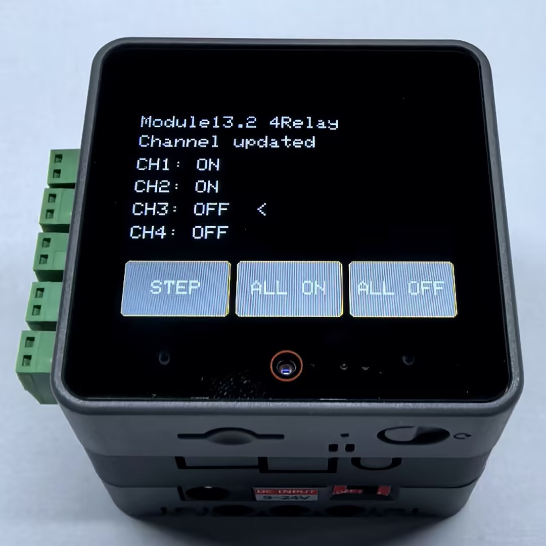
程序启动后,CoreS3 屏幕会显示 4 路继电器状态,< 表示当前待切换的通道。
- 点击
STEP:切换当前通道,随后自动选择下一通道。 - 点击
ALL ON:打开 4 路继电器。 - 点击
ALL OFF:关闭 4 路继电器。
请先使用万用表或符合规格的低压直流负载验证 COM 和 NO 端子的通断状态,再接入实际负载。
Page Tools