

Arduino 上手教程
2. 设备开发 & 案例程序
3. M5Unified
4. M5GFX
5. 扩展模块
Unit
Module
Atomic
Tab5
IoT
Module13.2 PPS Arduino 使用教程
1. 准备工作
- 环境配置:参考 Arduino IDE 上手教程 完成 IDE 安装,并根据使用的主机安装对应的板管理和驱动。
- 使用到的驱动库:
- 使用到的硬件:
- CoreS3
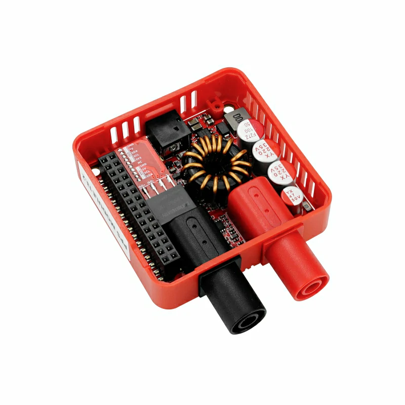
- Module13.2 PPS
- DC 9 ~ 36V 外部电源

2. 注意事项
外部供电
Module13.2 PPS 必须连接 DC 9 ~ 36V 外部电源,否则模块无法正常工作,并会在主机屏幕上提示
No i2c device。实际最大输出能力取决于输入电源、负载及连接线的承载能力。引脚兼容性
由于每款主机的引脚配置不同,使用前请参考产品文档中的引脚兼容表,并根据实际引脚连接情况修改案例程序。
3. 案例程序
- 本教程中使用的主控设备为 CoreS3,搭配 Module13.2 PPS 实现供电调节控制。Module13.2 PPS 使用 I2C 通讯,请根据实际的电路连接修改程序中的引脚定义,设备连接后对应的 I2C IO 为
G12 (SDA)、G11 (SCL)。
cpp
1 2 3 4 5 6 7 8 9 10 11 12 13 14 15 16 17 18 19 20 21 22 23 24 25 26 27 28 29 30 31 32 33 34 35 36 37 38 39 40 41 42 43 44 45 46 47 48 49 50 51 52 53 54 55 56 57 58 59 60 61 62 63 64 65 66 67 68 69 70 71 72 73 74 75 76 77 78 79 80 81 82 83 84 85 86 87 88
#include <M5Unified.h>
#include <M5GFX.h>
#include "M5ModulePPS.h"

M5GFX display;
M5Canvas canvas(&display);
M5ModulePPS pps;

// PPS output voltage target and current limit.
#define OUTPUT_VOLTAGE 5.0f
#define OUTPUT_CURRENT 5.0f

void setup() {
    M5.begin();
    display.begin();

    // Create a full-screen canvas for flicker-free updates.
    canvas.setFont(&fonts::FreeMonoBoldOblique12pt7b);
    canvas.createSprite(display.width(), display.height());

    // Retry until the PPS responds on the CoreS3 internal I2C bus.
    while (!pps.begin(&Wire, M5.In_I2C.getSDA(), M5.In_I2C.getSCL(),
                      MODULE_POWER_ADDR, 400000U)) {
        Serial.println("module pps connect error");
        canvas.clear(BLACK);
        canvas.setTextColor(RED);
        canvas.drawCenterString("No i2c device", display.width() / 2,
                                display.height() / 2);
        canvas.pushSprite(0, 0);
        delay(100);
    }

    // Apply both setpoints before enabling the power output.
    pps.setOutputVoltage(OUTPUT_VOLTAGE);
    pps.setOutputCurrent(OUTPUT_CURRENT);
    pps.setPowerEnable(true);
}

void loop() {
    // Read the live input, output, temperature, and regulation state.
    float voltage_readback = pps.getReadbackVoltage();
    float current_readback = pps.getReadbackCurrent();
    float temperature      = pps.getTemperature();
    float vin              = pps.getVIN();
    uint8_t mode           = pps.getMode();

    // Render one complete status frame before updating the display.
    canvas.fillSprite(BLACK);
    canvas.setFont(&fonts::FreeMonoBold12pt7b);
    canvas.setTextColor(WHITE);
    canvas.drawCenterString("Module PPS", display.width() / 2, 0);

    canvas.setCursor(10, 40);
    canvas.setTextColor(WHITE);
    canvas.printf("VIN: ");
    canvas.setTextColor(GREEN);
    canvas.printf("%.2fV", vin);

    canvas.setCursor(10, 80);
    canvas.setTextColor(WHITE);
    canvas.printf("Mode: ");
    canvas.setTextColor(GREEN);
    // The PPS switches between CV and CC automatically as the load changes.
    if (mode <= 1)
        canvas.printf("Constant Voltage");
    else
        canvas.printf("Constant Current");

    canvas.setTextColor(WHITE);
    canvas.setCursor(10, 120);
    canvas.printf("Voltage: ");
    canvas.setTextColor(GREEN);
    canvas.printf("%.2fV", voltage_readback);

    canvas.setCursor(10, 160);
    canvas.setTextColor(WHITE);
    canvas.printf("Current: ");
    canvas.setTextColor(GREEN);
    canvas.printf("%.2fA", current_readback);

    canvas.setCursor(10, 200);
    canvas.setTextColor(WHITE);
    canvas.printf("Temperature: ");
    canvas.setTextColor(GREEN);
    canvas.printf("%.2fC", temperature);

    canvas.pushSprite(0, 0);
}4. 编译上传
- 1. 进入下载模式:CoreS3 长按复位按键 (大约 2 秒) 直到内部绿色 LED 灯亮起后松开按键。松开后绿色 LED 灯熄灭,表示设备已进入下载模式,等待烧录。
说明
不同设备进行程序烧录前需要进入下载模式,不同的主控设备该步骤可能有所不同。详情可参考Arduino IDE上手教程页面底部的设备程序下载教程列表,查看具体的操作方式。
.gif)
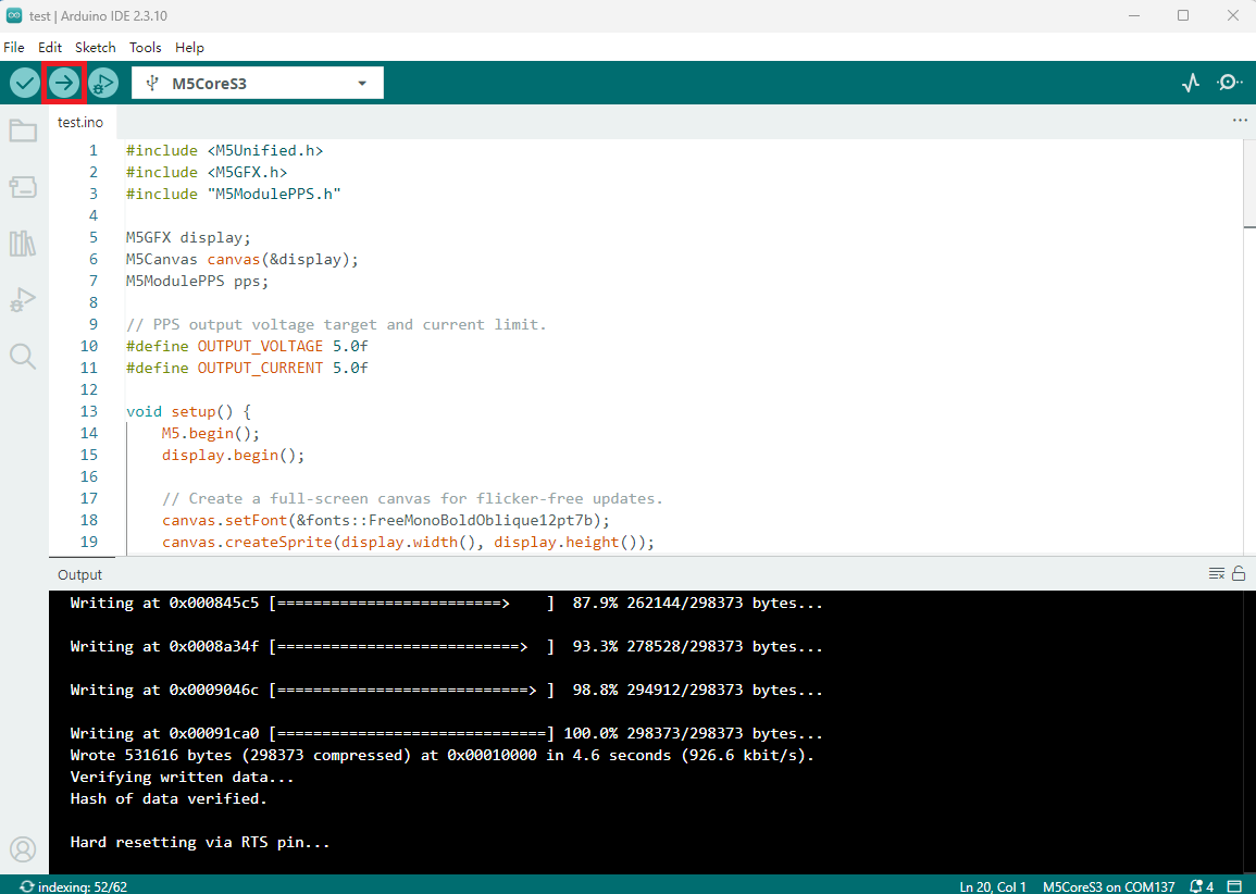
- 选中设备端口,点击 Arduino IDE 左上角编译上传按钮,等待程序完成编译并上传至设备。
5. 功能验证
- 上电后,CoreS3 会初始化 Module13.2 PPS 模块,设置 5.0V 输出电压和 5.0A 电流上限并开启输出,然后在屏幕上持续显示输入电压、CV/CC 模式、输出电压、输出电流和模块温度。
说明
PPS 模块会根据负载自动切换工作状态:负载电流未达到限流值时工作在恒压模式 (
Constant Voltage);负载试图超过限流值时,模块会降低输出电压并进入恒流模式 (Constant Current)。getMode() 仅用于读取当前状态,不用于手动切换模式。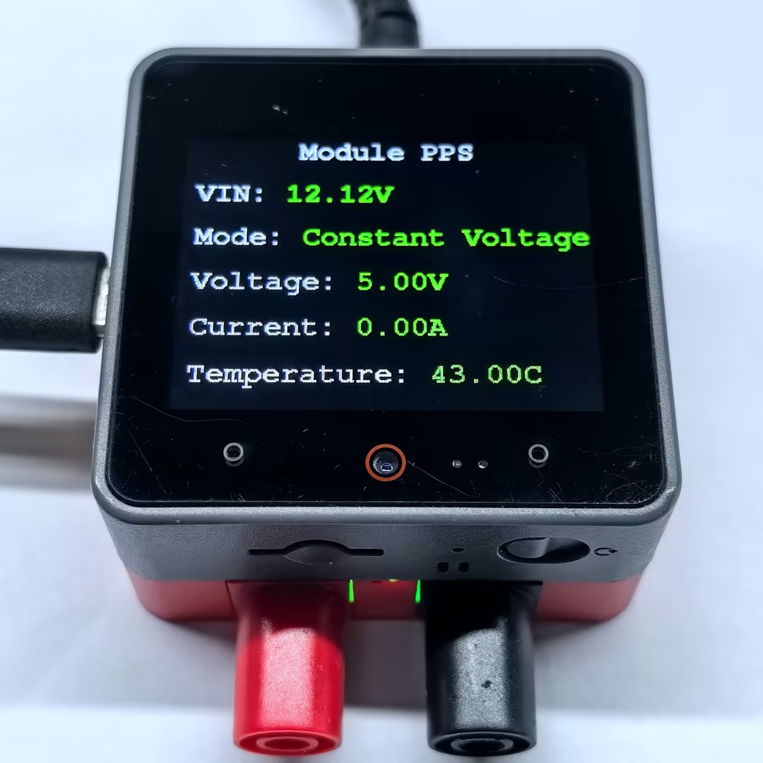
Page Tools