

Arduino入門
2. デバイス&サンプル
3. M5Unified
4. M5GFX
5. 拡張モジュール&サンプル
Unit
Module
Atomic
Tab5
IoT
アクセサリー
Module13.2 4Relay v1.1 Arduino 使用手順
1. 準備作業
- 環境設定: Arduino IDE 入門チュートリアルを参照して IDE のインストールを完了し、使用するメインコントローラに対応するボード管理とドライバをインストールしてください。
- 使用するドライバライブラリ:
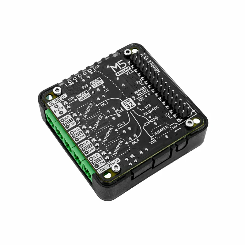
- 使用するハードウェア製品:

2. 注意事項
負荷と配線
Module13.2 4Relay v1.1 は DC 回路のオン/オフにのみ対応しています。4 チャンネルの最大負荷容量は 24W (DC 24V@1A) です。リレー端子は
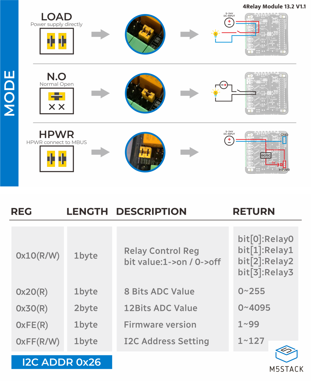
COM と NO です。実際の負荷と電源の仕様に従って配線してください。配線、配線の取り外し、または負荷の交換を行う前に、必ず電源を切ってください。動作モード
製品の配線説明書に従ってジャンパーキャップを取り付け、有源または無源モードを選択してください。外部 DC 5 ~ 24V 電源を使用する場合は、電源の極性と負荷電圧が製品仕様を満たしていることを確認してください。本モジュールに AC 電源を接続しないでください。
ピン互換性
ホストデバイスによって I2C ピン構成が異なるため、使用前に製品ドキュメントのピン互換性表を参照し、実際の接続に合わせてサンプルプログラムを修正してください。
3. サンプルプログラム
本チュートリアルでは、CoreS3 と Module13.2 4Relay v1.1 を組み合わせて使用します。本モジュールは I2C で通信し、デフォルトアドレスは 0x26 です。CoreS3 に接続する I2C ピンは G12 (SDA) と G11 (SCL) です。CoreS3 のタッチスクリーンでリレーを制御します。STEP をタップすると現在のチャンネルを切り替え、ALL ON をタップするとすべてのチャンネルをオンにし、ALL OFF をタップするとすべてのチャンネルをオフにします。
cpp
1 2 3 4 5 6 7 8 9 10 11 12 13 14 15 16 17 18 19 20 21 22 23 24 25 26 27 28 29 30 31 32 33 34 35 36 37 38 39 40 41 42 43 44 45 46 47 48 49 50 51 52 53 54 55 56 57 58 59 60 61 62 63 64 65 66 67 68 69 70 71 72 73 74 75 76 77 78 79 80 81 82 83 84 85 86 87 88 89 90 91 92 93 94 95 96 97 98 99 100 101 102 103 104 105 106 107 108 109 110 111 112 113 114 115 116 117 118 119 120 121 122 123 124 125 126 127
#include <M5Unified.h>
#include "Module_4RELAY.h"

MODULE_4RELAY relay;
TwoWire *relayWire = &Wire1;

uint8_t currentChannel = 0;

constexpr uint8_t RELAY_SDA = 12;
constexpr uint8_t RELAY_SCL = 11;
constexpr int16_t TOUCH_BUTTON_Y = 176;
constexpr int16_t TOUCH_BUTTON_HEIGHT = 58;
constexpr int16_t TOUCH_BUTTON_WIDTH = 100;
constexpr int16_t TOUCH_BUTTON_GAP = 6;

int16_t getButtonX(uint8_t index)
{
    return TOUCH_BUTTON_GAP + index * (TOUCH_BUTTON_WIDTH + TOUCH_BUTTON_GAP);
}

int8_t getTouchedButton(int16_t x, int16_t y)
{
    if (y < TOUCH_BUTTON_Y || y >= TOUCH_BUTTON_Y + TOUCH_BUTTON_HEIGHT) {
        return -1;
    }

    for (uint8_t index = 0; index < 3; ++index) {
        const int16_t buttonX = getButtonX(index);
        if (x >= buttonX && x < buttonX + TOUCH_BUTTON_WIDTH) {
            return index;
        }
    }
    return -1;
}

void drawTouchButton(uint8_t index, const char *label)
{
    const int16_t x = getButtonX(index);
    M5.Display.fillRoundRect(x, TOUCH_BUTTON_Y, TOUCH_BUTTON_WIDTH,
                             TOUCH_BUTTON_HEIGHT, 5, TFT_DARKGREY);
    M5.Display.drawRoundRect(x, TOUCH_BUTTON_Y, TOUCH_BUTTON_WIDTH,
                             TOUCH_BUTTON_HEIGHT, 5, TFT_ORANGE);
    M5.Display.setTextDatum(MC_DATUM);
    M5.Display.setTextColor(TFT_WHITE, TFT_DARKGREY);
    M5.Display.drawString(label, x + TOUCH_BUTTON_WIDTH / 2,
                          TOUCH_BUTTON_Y + TOUCH_BUTTON_HEIGHT / 2);
}

void showStatus(const char *action)
{
    const uint8_t state = relay.getAllRelayState();

    M5.Display.fillScreen(TFT_BLACK);
    M5.Display.setTextColor(TFT_WHITE, TFT_BLACK);
    M5.Display.setTextSize(2);
    M5.Display.setTextDatum(TL_DATUM);
    M5.Display.drawString("Module13.2 4Relay", 8, 8);
    M5.Display.drawString(action, 8, 32);

    for (uint8_t index = 0; index < 4; ++index) {
        const bool isOn = (state >> index) & 0x01;
        M5.Display.setCursor(8, 60 + index * 26);
        M5.Display.printf("CH%u: %s%s", index + 1, isOn ? "ON" : "OFF",
                          index == currentChannel ? "  <" : "");
    }

    Serial.printf("%s | relay state: 0x%02X\n", action, state);
    drawTouchButton(0, "STEP");
    drawTouchButton(1, "ALL ON");
    drawTouchButton(2, "ALL OFF");
}

void setup()
{
    M5.begin();
    Serial.begin(115200);

    while (!relay.begin(relayWire, MODULE_4RELAY_ADDR, RELAY_SDA, RELAY_SCL,
                        200000L)) {
        Serial.println("4RELAY INIT ERROR");
        M5.Display.fillScreen(TFT_BLACK);
        M5.Display.setTextColor(TFT_RED, TFT_BLACK);
        M5.Display.setTextSize(2);
        M5.Display.setTextDatum(TL_DATUM);
        M5.Display.drawString("4RELAY INIT ERROR", 8, 8);
        delay(1000);
    }

    Serial.println("4RELAY INIT SUCCESS");
    relay.setAllRelay(false);
    showStatus("Ready");
}

void loop()
{
    M5.update();

    const auto touch = M5.Touch.getDetail();
    if (touch.wasClicked()) {
        switch (getTouchedButton(touch.x, touch.y)) {
        case 0: {
            const bool nextState = !relay.getRelayState(currentChannel);
            const bool success = relay.setRelay(currentChannel, nextState);
            currentChannel = (currentChannel + 1) % 4;
            showStatus(success ? "Channel updated" : "Channel update error");
            break;
        }

        case 1: {
            const bool success = relay.setAllRelay(true);
            showStatus(success ? "All ON" : "All ON error");
            break;
        }

        case 2: {
            const bool success = relay.setAllRelay(false);
            showStatus(success ? "All OFF" : "All OFF error");
            break;
        }

        default:
            break;
        }
    }

    delay(20);
}4. コンパイルと書き込み
- 1. ダウンロードモードに入る: CoreS3 のリセットボタンを約 2 秒間長押しし、内部の緑色 LED が点灯したらボタンを離します。デバイスはダウンロードモードに入り、プログラムの書き込みを待機します。
説明
プログラムを書き込む前に、デバイスによってはダウンロードモードに入る必要があります。手順はメインコントローラによって異なる場合があります。詳細はArduino IDE 入門チュートリアルページ下部のデバイスプログラムダウンロードチュートリアルリストを参照してください。
.gif)
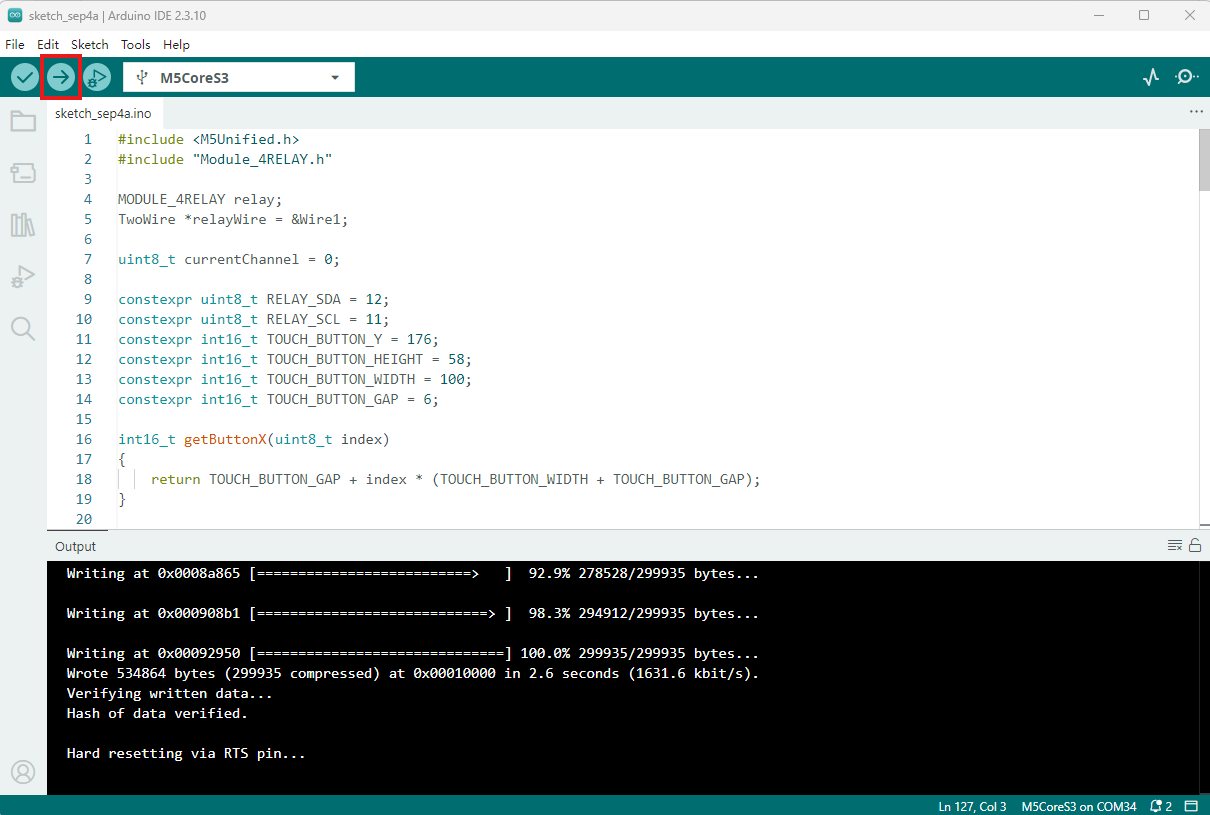
- 2. デバイスポートを選択し、Arduino IDE の左上にあるコンパイル&アップロードボタンをクリックします。プログラムのコンパイルとデバイスへのアップロードが完了するまで待ちます。
5. リレー制御
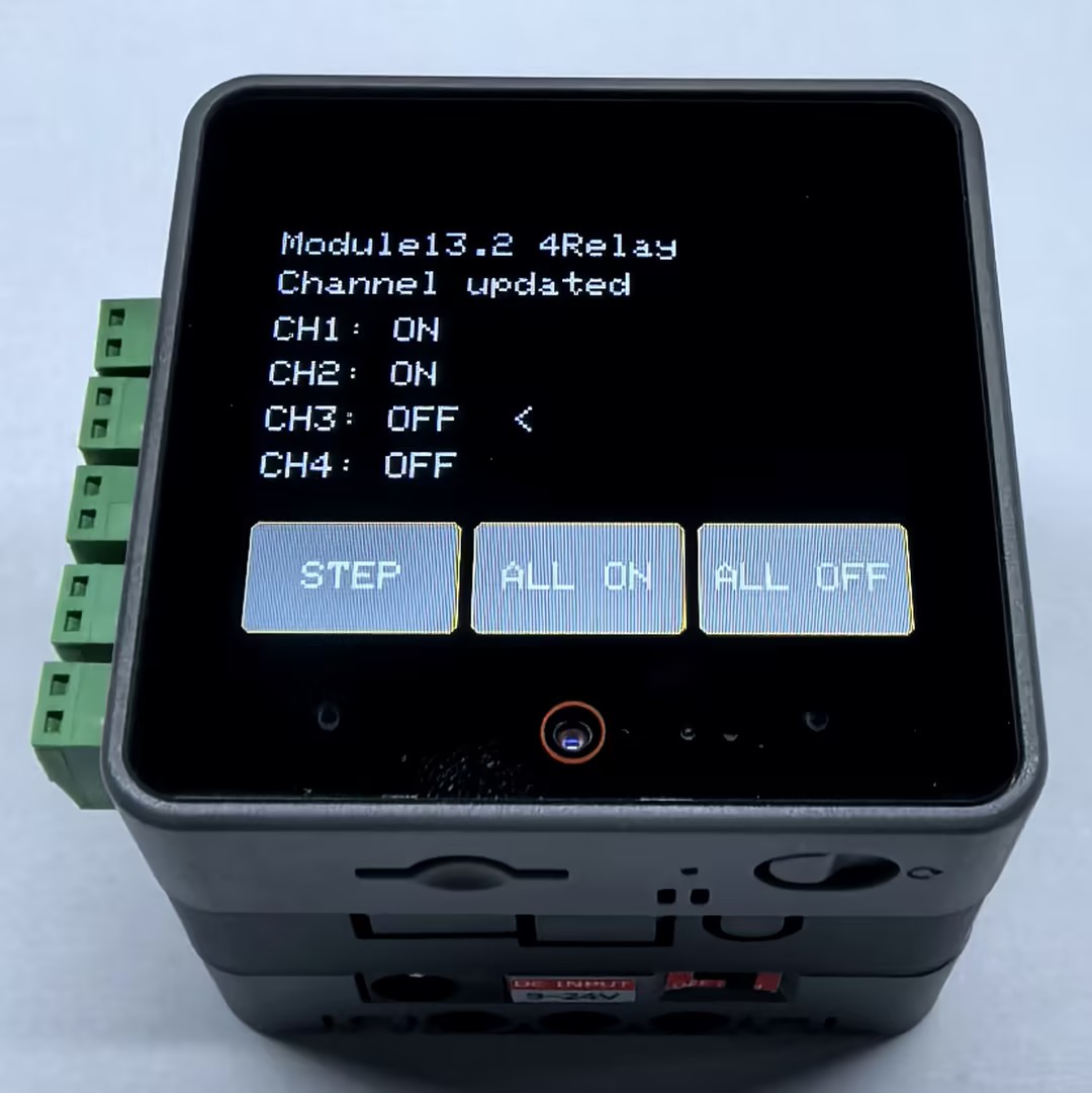
プログラムを起動すると、CoreS3 の画面に 4 つのリレーの状態が表示されます。< は次に切り替えるチャンネルを示します。
STEPをタップ: 現在のチャンネルを切り替え、次のチャンネルを自動的に選択します。ALL ONをタップ: 4 つのリレーをすべてオンにします。ALL OFFをタップ: 4 つのリレーをすべてオフにします。
実際の負荷を接続する前に、テスターまたは仕様に適合した低電圧 DC 負荷を使用して、COM と NO 端子間の導通を確認してください。
Page Tools