Arduino入門
2. デバイス&サンプル
3. M5Unified
4. M5GFX
5. 拡張モジュール&サンプル
Unit
Module
Atomic
Tab5
IoT
アクセサリー
Unit 8Servos2-I2C Arduino 使用チュートリアル
1. 準備
環境設定:Arduino IDE 入門ガイドを参照して IDE をインストールし、使用する開発ボードに対応したボードパッケージとドライバライブラリをインストールしてください。
使用するライブラリ:
使用するハードウェア:

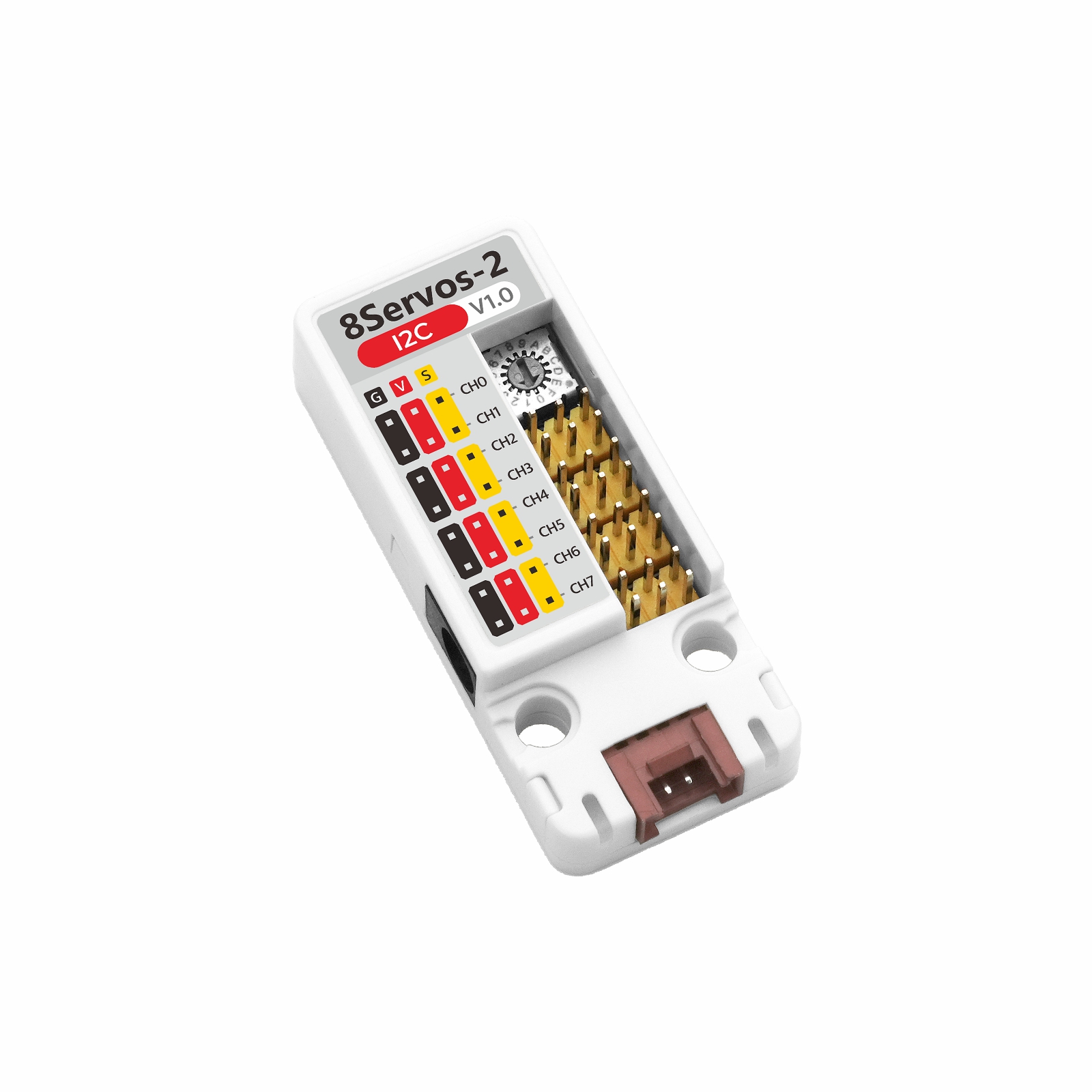
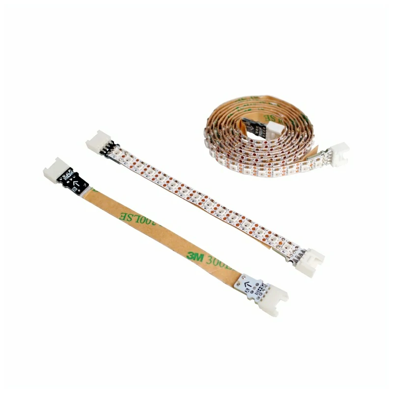
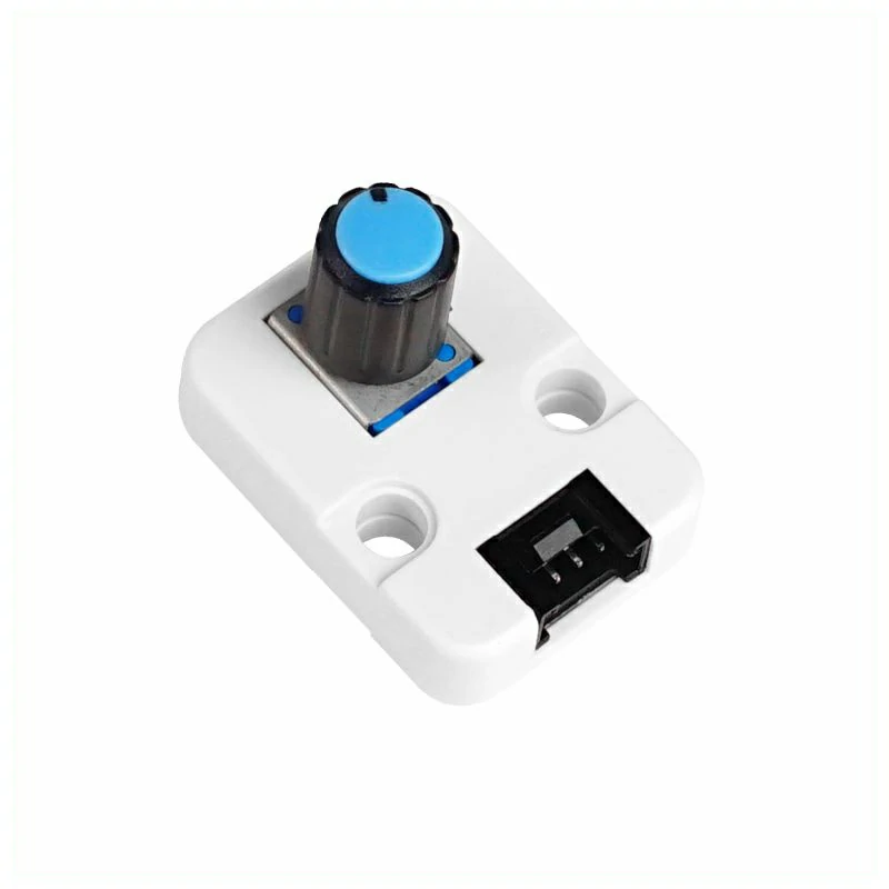
2. 注意事項
3. サンプルプログラム
- このチュートリアルでは、CoreS3 と Unit 8Servos2-I2C を使用してサーボを制御します。Unit 8Servos2-I2C は I2C 通信を使用します。接続時の対応ピンは
G2 (SDA)とG1 (SCL)です。
0x25 で、Unit のアドレスダイヤルの設定 0 に対応します。
ダイヤルを別の位置に設定した場合は、プログラムの UNIT_I2C_ADDRESS を対応するアドレスに変更してください。setup() 内で cfg.output_power を true に設定してください。3.1 サーボ制御
#include <M5Unified.h>
#include <M5Unit8Servos2.h>

constexpr int I2C_SDA_PIN             = 2;
constexpr int I2C_SCL_PIN             = 1;
constexpr uint8_t UNIT_I2C_ADDRESS    = UNIT_8SERVOS2_DEFAULT_ADDR;
constexpr uint8_t SERVO_CHANNEL_COUNT = 8;
constexpr uint32_t I2C_FREQUENCY      = 400000;
constexpr int16_t STATUS_LINE_HEIGHT  = 40;

// Store the Unit controller and current servo position.
M5Unit8Servos2 servos2;
M5Canvas canvas(&M5.Display);
int16_t angle     = 0;
int8_t angle_step = 20;

// Refresh the display with servo and power data.
void drawStatus(uint16_t dc_voltage, uint16_t grove_voltage, uint16_t current_mA)
{
    canvas.fillScreen(TFT_BLACK);
    canvas.setCursor(0, 0);
    canvas.printf("Unit 8Servos2-I2C\n");
    canvas.setCursor(0, STATUS_LINE_HEIGHT);
    canvas.printf("Angle: %d deg", angle);
    canvas.setCursor(0, STATUS_LINE_HEIGHT * 2);
    canvas.printf("DC: %umV", static_cast<unsigned>(dc_voltage));
    canvas.setCursor(0, STATUS_LINE_HEIGHT * 3);
    canvas.printf("Current: %umA", static_cast<unsigned>(current_mA));
    canvas.setCursor(0, STATUS_LINE_HEIGHT * 4);
    canvas.printf("Grove: %umV", static_cast<unsigned>(grove_voltage));
    canvas.pushSprite(0, 0);
}

void setup()
{
    auto cfg = M5.config();
    cfg.output_power = false;
    M5.begin(cfg);
    canvas.createSprite(M5.Display.width(), M5.Display.height());
    Serial.begin(115200);
    canvas.setFont(&fonts::FreeMonoBold12pt7b);
    canvas.setTextColor(TFT_WHITE, TFT_BLACK);

    Wire.begin(I2C_SDA_PIN, I2C_SCL_PIN, I2C_FREQUENCY);
    while (!servos2.begin(&Wire, UNIT_I2C_ADDRESS, -1, -1, I2C_FREQUENCY)) {
        Serial.println("Unit 8Servos2-I2C not found");
        canvas.fillScreen(TFT_BLACK);
        canvas.setCursor(0, 0);
        canvas.printf("Unit not found");
        canvas.setCursor(0, STATUS_LINE_HEIGHT);
        canvas.printf("Check I2C and address");
        canvas.pushSprite(0, 0);
        delay(1000);
    }

    // Set all channels to servo mode.
    for (uint8_t channel = 0; channel < SERVO_CHANNEL_COUNT; ++channel) {
        servos2.setMode(channel, M5_8SERVOS2_MODE_SERVO);
    }

    // Set both PWM timers to 50 Hz for standard servos.
    servos2.setTimerFrequency(0, 50);
    servos2.setTimerFrequency(1, 50);

    // Read the initial power telemetry.
    const uint16_t dc_voltage    = servos2.getDCVoltage();
    const uint16_t grove_voltage = servos2.getGroveVoltage();
    const uint16_t current_mA    = servos2.getSysCurrent();
    Serial.println("Unit 8Servos2-I2C ready");
    drawStatus(dc_voltage, grove_voltage, current_mA);
}

void loop()
{
    // Apply the current angle to all servo channels.
    for (uint8_t channel = 0; channel < SERVO_CHANNEL_COUNT; ++channel) {
        servos2.setServoAngle(channel, static_cast<uint8_t>(angle));
    }

    // Read and report the latest power telemetry.
    const uint16_t dc_voltage    = servos2.getDCVoltage();
    const uint16_t grove_voltage = servos2.getGroveVoltage();
    const uint16_t current_mA    = servos2.getSysCurrent();
    Serial.printf(
        "Servo angle: %d deg, DC: %u mV, Grove: %u mV, Current: %u mA\n", angle,
        static_cast<unsigned>(dc_voltage), static_cast<unsigned>(grove_voltage),
        static_cast<unsigned>(current_mA));
    drawStatus(dc_voltage, grove_voltage, current_mA);

    // Sweep the servos between 0 and 180 degrees.
    angle += angle_step;
    if (angle >= 180) {
        angle      = 180;
        angle_step = -20;
    } else if (angle <= 0) {
        angle      = 0;
        angle_step = 20;
    }

    delay(200);
}起動後、プログラムは 8 チャンネルすべてをサーボモードに設定し、50Hz でサーボを制御します。サーボは 20° 刻みで 0° ~ 180° の間を同期して動作します。ディスプレイには現在の角度、DC 入力電圧、システム電流、Grove ポート電圧が表示され、シリアル出力にも同じデータが出力されます。
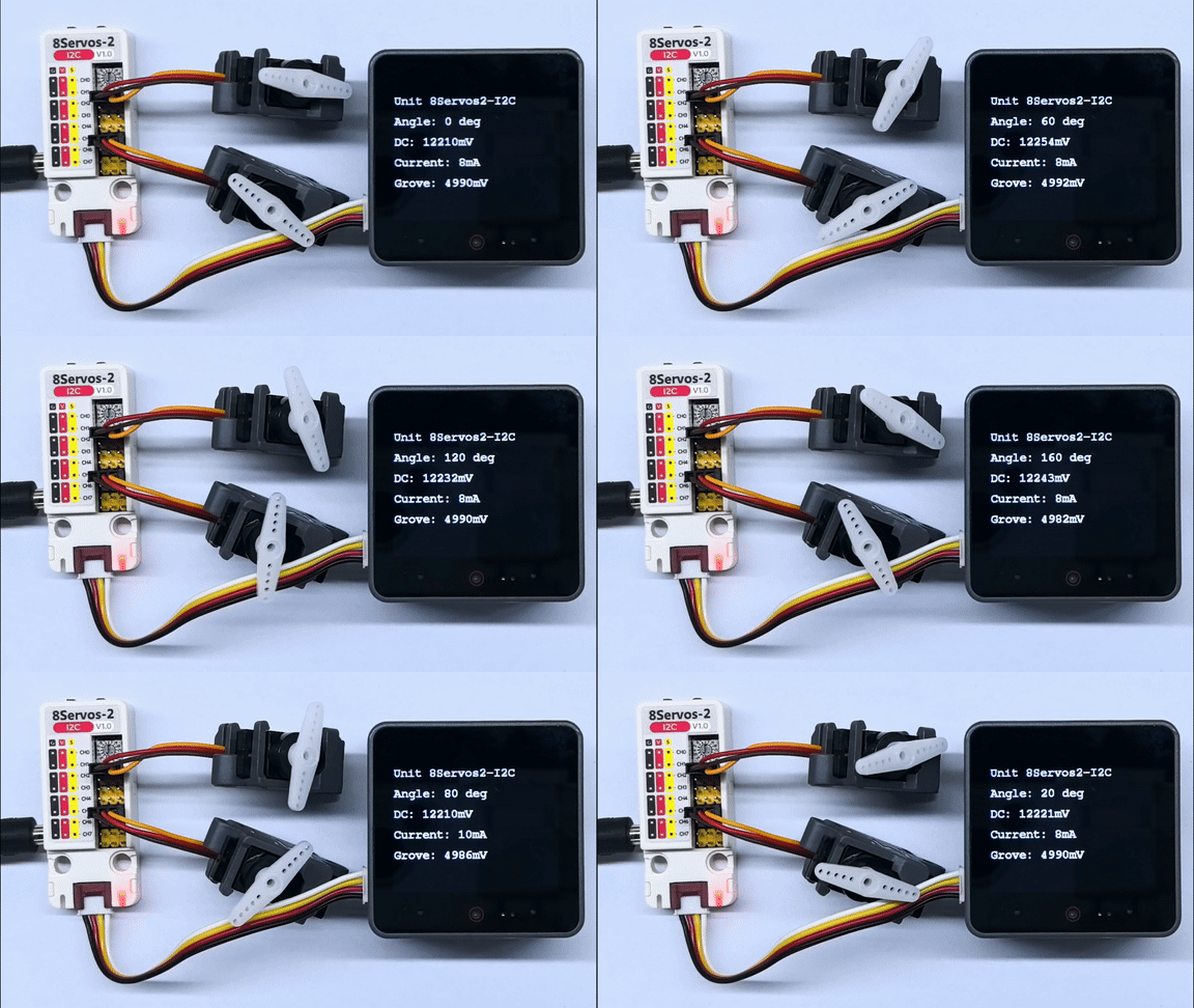
シリアル出力例:
Unit 8Servos2-I2C ready
Servo angle: 0 deg, DC: 12298 mV, Grove: 5024 mV, Current: 8 mA
Servo angle: 20 deg, DC: 12309 mV, Grove: 5026 mV, Current: 8 mA
Servo angle: 40 deg, DC: 12298 mV, Grove: 5024 mV, Current: 8 mA
Servo angle: 60 deg, DC: 12298 mV, Grove: 5024 mV, Current: 8 mA
Servo angle: 80 deg, DC: 12298 mV, Grove: 5024 mV, Current: 8 mA
Servo angle: 100 deg, DC: 12298 mV, Grove: 5024 mV, Current: 6 mA
Servo angle: 120 deg, DC: 12298 mV, Grove: 5030 mV, Current: 8 mA
Servo angle: 140 deg, DC: 12287 mV, Grove: 5022 mV, Current: 8 mA
Servo angle: 160 deg, DC: 12298 mV, Grove: 5028 mV, Current: 8 mA
Servo angle: 180 deg, DC: 12298 mV, Grove: 5030 mV, Current: 8 mA3.2 入出力制御
#include <M5Unified.h>
#include <M5Unit8Servos2.h>

constexpr int I2C_SDA_PIN             = 2;
constexpr int I2C_SCL_PIN             = 1;
constexpr uint8_t UNIT_I2C_ADDRESS    = UNIT_8SERVOS2_DEFAULT_ADDR;
constexpr uint32_t I2C_FREQUENCY      = 400000;
constexpr int16_t STATUS_LINE_HEIGHT  = 40;

M5Unit8Servos2 servos2;
M5Canvas canvas(&M5.Display);
bool output_ch0 = false;
bool output_ch4 = true;

void drawStatus(bool input_ch3, bool input_ch7)
{
    canvas.fillScreen(TFT_BLACK);
    canvas.setCursor(0, 0);
    canvas.printf("Unit 8Servos2-I2C\n");
    canvas.setCursor(0, STATUS_LINE_HEIGHT);
    canvas.printf("CH0 OUT: %s", output_ch0 ? "HIGH" : "LOW");
    canvas.setCursor(0, STATUS_LINE_HEIGHT * 2);
    canvas.printf("CH4 OUT: %s", output_ch4 ? "HIGH" : "LOW");
    canvas.setCursor(0, STATUS_LINE_HEIGHT * 3);
    canvas.printf("CH3 IN:  %s", input_ch3 ? "HIGH" : "LOW");
    canvas.setCursor(0, STATUS_LINE_HEIGHT * 4);
    canvas.printf("CH7 IN:  %s", input_ch7 ? "HIGH" : "LOW");
    canvas.pushSprite(0, 0);
}

void setup()
{
    auto cfg = M5.config();
    cfg.output_power = false;
    M5.begin(cfg);
    canvas.createSprite(M5.Display.width(), M5.Display.height());
    Serial.begin(115200);
    canvas.setFont(&fonts::FreeMonoBold12pt7b);
    canvas.setTextColor(TFT_WHITE, TFT_BLACK);

    Wire.begin(I2C_SDA_PIN, I2C_SCL_PIN, I2C_FREQUENCY);
    while (!servos2.begin(&Wire, UNIT_I2C_ADDRESS, -1, -1, I2C_FREQUENCY)) {
        Serial.println("Unit 8Servos2-I2C not found");
        canvas.fillScreen(TFT_BLACK);
        canvas.setCursor(0, 0);
        canvas.printf("Unit not found");
        canvas.setCursor(0, STATUS_LINE_HEIGHT);
        canvas.printf("Check I2C and address");
        canvas.pushSprite(0, 0);
        delay(1000);
    }

    // Configure output and input channels.
    servos2.setMode(0, M5_8SERVOS2_MODE_OUTPUT);
    servos2.setMode(4, M5_8SERVOS2_MODE_OUTPUT);
    servos2.setMode(3, M5_8SERVOS2_MODE_INPUT);
    servos2.setMode(7, M5_8SERVOS2_MODE_INPUT);
    servos2.setInputPull(3, M5_8SERVOS2_PULL_UP);
    servos2.setInputPull(7, M5_8SERVOS2_PULL_UP);
}

void loop()
{
    // Set opposite output levels and read the input levels.
    servos2.setDigitalOutput(0, output_ch0);
    servos2.setDigitalOutput(4, output_ch4);
    const bool input_ch3 = servos2.getDigitalInput(3);
    const bool input_ch7 = servos2.getDigitalInput(7);

    Serial.printf("CH0: %s, CH4: %s, CH3: %s, CH7: %s\n",
                  output_ch0 ? "HIGH" : "LOW", output_ch4 ? "HIGH" : "LOW",
                  input_ch3 ? "HIGH" : "LOW", input_ch7 ? "HIGH" : "LOW");
    drawStatus(input_ch3, input_ch7);

    output_ch0 = !output_ch0;
    output_ch4 = !output_ch0;
    delay(500);
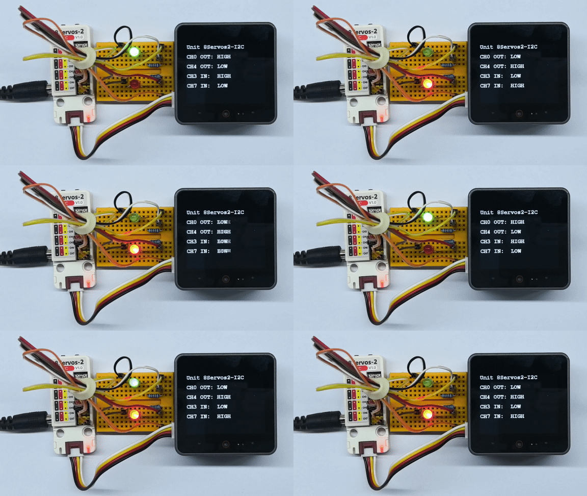
}CH0 と CH4 に接続した外付け LED は、互いに逆の点灯状態を保ちながら、約 500ms ごとに点灯と消灯を切り替えます。デモでは CH3 を CH0 に、CH7 を CH4 に外部配線で接続し、それぞれの HIGH/LOW レベルを読み取ります。ディスプレイとシリアル出力には、2 チャンネルの出力状態と 2 チャンネルの入力レベルが表示されます。
3.3 ADC 測定
#include <M5Unified.h>
#include <M5Unit8Servos2.h>

constexpr int I2C_SDA_PIN             = 2;
constexpr int I2C_SCL_PIN             = 1;
constexpr uint8_t UNIT_I2C_ADDRESS    = UNIT_8SERVOS2_DEFAULT_ADDR;
constexpr uint32_t I2C_FREQUENCY      = 400000;
constexpr int16_t STATUS_LINE_HEIGHT  = 40;

M5Unit8Servos2 servos2;
M5Canvas canvas(&M5.Display);

void drawStatus(uint16_t adc_raw, uint16_t voltage_mV)
{
    canvas.fillScreen(TFT_BLACK);
    canvas.setCursor(0, 0);
    canvas.printf("Unit 8Servos2-I2C\n");
    canvas.setCursor(0, STATUS_LINE_HEIGHT);
    canvas.printf("Channel: CH4");
    canvas.setCursor(0, STATUS_LINE_HEIGHT * 2);
    canvas.printf("ADC Raw: %u", static_cast<unsigned>(adc_raw));
    canvas.setCursor(0, STATUS_LINE_HEIGHT * 3);
    canvas.printf("Voltage: %umV", static_cast<unsigned>(voltage_mV));
    canvas.pushSprite(0, 0);
}

void setup()
{
    auto cfg = M5.config();
    cfg.output_power = false;
    M5.begin(cfg);
    canvas.createSprite(M5.Display.width(), M5.Display.height());
    Serial.begin(115200);
    canvas.setFont(&fonts::FreeMonoBold12pt7b);
    canvas.setTextColor(TFT_WHITE, TFT_BLACK);

    Wire.begin(I2C_SDA_PIN, I2C_SCL_PIN, I2C_FREQUENCY);
    while (!servos2.begin(&Wire, UNIT_I2C_ADDRESS, -1, -1, I2C_FREQUENCY)) {
        Serial.println("Unit 8Servos2-I2C not found");
        canvas.fillScreen(TFT_BLACK);
        canvas.setCursor(0, 0);
        canvas.printf("Unit not found");
        canvas.setCursor(0, STATUS_LINE_HEIGHT);
        canvas.printf("Check I2C and address");
        canvas.pushSprite(0, 0);
        delay(1000);
    }

    // Configure CH4 for ADC input.
    servos2.setMode(4, M5_8SERVOS2_MODE_ADC);
}

void loop()
{
    // Read the latest raw ADC value and voltage.
    const uint16_t adc_raw    = servos2.getADCRaw(4);
    const uint16_t voltage_mV = servos2.getVoltageMV(4);
    Serial.printf("CH4 ADC: %u, Voltage: %umV\n", static_cast<unsigned>(adc_raw),
                  static_cast<unsigned>(voltage_mV));
    drawStatus(adc_raw, voltage_mV);
    delay(200);
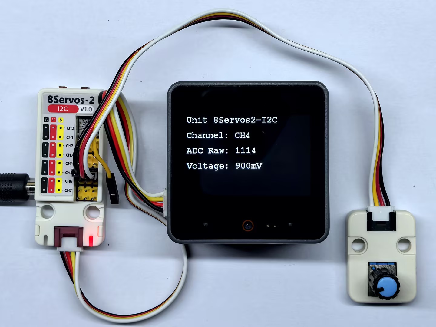
}起動後、プログラムは CH4 を ADC モードに設定し、ADC 生データと換算後の電圧値を継続的に読み取ります。CoreS3 のディスプレイには CH4 の ADC 値と電圧が表示され、シリアルポートにも測定結果が出力されます。
3.4 PWM 出力
#include <M5Unified.h>
#include <M5Unit8Servos2.h>

constexpr int I2C_SDA_PIN             = 2;
constexpr int I2C_SCL_PIN             = 1;
constexpr uint8_t UNIT_I2C_ADDRESS    = UNIT_8SERVOS2_DEFAULT_ADDR;
constexpr uint32_t I2C_FREQUENCY      = 400000;
constexpr uint16_t PWM_FREQUENCY      = 1000;
constexpr int16_t STATUS_LINE_HEIGHT  = 40;

M5Unit8Servos2 servos2;
M5Canvas canvas(&M5.Display);
uint8_t duty_ch0 = 0;
uint8_t duty_ch4 = 100;
int8_t duty_step = 10;

void drawStatus()
{
    canvas.fillScreen(TFT_BLACK);
    canvas.setCursor(0, 0);
    canvas.printf("Unit 8Servos2-I2C\n");
    canvas.setCursor(0, STATUS_LINE_HEIGHT);
    canvas.printf("CH0: %u%%", static_cast<unsigned>(duty_ch0));
    canvas.setCursor(0, STATUS_LINE_HEIGHT * 2);
    canvas.printf("CH4: %u%%", static_cast<unsigned>(duty_ch4));
    canvas.setCursor(0, STATUS_LINE_HEIGHT * 3);
    canvas.printf("Frequency: %uHz", static_cast<unsigned>(PWM_FREQUENCY));
    canvas.pushSprite(0, 0);
}

void setup()
{
    auto cfg = M5.config();
    cfg.output_power = false;
    M5.begin(cfg);
    canvas.createSprite(M5.Display.width(), M5.Display.height());
    Serial.begin(115200);
    canvas.setFont(&fonts::FreeMonoBold12pt7b);
    canvas.setTextColor(TFT_WHITE, TFT_BLACK);

    Wire.begin(I2C_SDA_PIN, I2C_SCL_PIN, I2C_FREQUENCY);
    while (!servos2.begin(&Wire, UNIT_I2C_ADDRESS, -1, -1, I2C_FREQUENCY)) {
        Serial.println("Unit 8Servos2-I2C not found");
        canvas.fillScreen(TFT_BLACK);
        canvas.setCursor(0, 0);
        canvas.printf("Unit not found");
        canvas.setCursor(0, STATUS_LINE_HEIGHT);
        canvas.printf("Check I2C and address");
        canvas.pushSprite(0, 0);
        delay(1000);
    }

    // Configure CH0 and CH4 for PWM output.
    servos2.setMode(0, M5_8SERVOS2_MODE_PWM);
    servos2.setMode(4, M5_8SERVOS2_MODE_PWM);
    servos2.setTimerFrequency(0, PWM_FREQUENCY);
    servos2.setTimerFrequency(1, PWM_FREQUENCY);
}

void loop()
{
    // Apply opposite duty cycles to CH0 and CH4.
    servos2.setPWMDuty(0, duty_ch0);
    servos2.setPWMDuty(4, duty_ch4);
    Serial.printf("CH0: %u%%, CH4: %u%%\n", static_cast<unsigned>(duty_ch0),
                  static_cast<unsigned>(duty_ch4));
    drawStatus();

    if (duty_ch0 >= 100) {
        duty_step = -10;
    } else if (duty_ch0 == 0) {
        duty_step = 10;
    }
    duty_ch0 = static_cast<uint8_t>(duty_ch0 + duty_step);
    duty_ch4 = 100 - duty_ch0;
    delay(50);
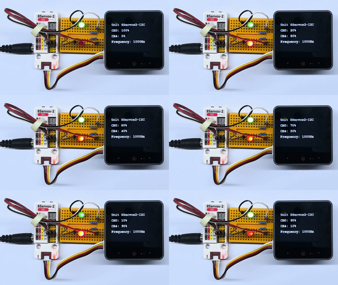
}CH0 と CH4 に接続した外付け LED は、一方が徐々に明るくなると、もう一方が徐々に暗くなります。最大の明るさまたは消灯状態に達すると、明るさの変化方向が反転します。明るさは約 50ms ごとに更新されます。ディスプレイには両チャンネルのデューティ比と 1000Hz の出力周波数が表示され、シリアルポートには両チャンネルのデューティ比が出力されます。
3.5 RGB LED 制御
#include <M5Unified.h>
#include <M5Unit8Servos2.h>

constexpr int I2C_SDA_PIN             = 2;
constexpr int I2C_SCL_PIN             = 1;
constexpr uint8_t UNIT_I2C_ADDRESS    = UNIT_8SERVOS2_DEFAULT_ADDR;
constexpr uint8_t RGB_CHANNEL         = 2;
constexpr uint8_t RGB_LED_COUNT       = 15;
constexpr uint8_t RGB_BRIGHTNESS_PERCENT = 5;
constexpr uint32_t I2C_FREQUENCY      = 400000;
constexpr int16_t STATUS_LINE_HEIGHT  = 40;

M5Unit8Servos2 servos2;
M5Canvas canvas(&M5.Display);

uint32_t colorWheel(uint8_t position)
{
    position = 255 - position;
    if (position < 85) {
        return ((255 - position * 3) << 16) | (position * 3);
    }
    if (position < 170) {
        position -= 85;
        return (position * 3 << 8) | (255 - position * 3);
    }
    position -= 170;
    return (position * 3 << 16) | (255 - position * 3 << 8);
}

void showStatus(const char *mode)
{
    canvas.fillScreen(TFT_BLACK);
    canvas.setCursor(0, 0);
    canvas.printf("Unit 8Servos2-I2C\n");
    canvas.setCursor(0, STATUS_LINE_HEIGHT);
    canvas.printf("Channel: CH2");
    canvas.setCursor(0, STATUS_LINE_HEIGHT * 2);
    canvas.printf("Mode: %s", mode);
    canvas.setCursor(0, STATUS_LINE_HEIGHT * 3);
    canvas.printf("LEDs: %u", static_cast<unsigned>(RGB_LED_COUNT));
    canvas.setCursor(0, STATUS_LINE_HEIGHT * 4);
    canvas.printf("Brightness: %u%%", static_cast<unsigned>(RGB_BRIGHTNESS_PERCENT));
    canvas.pushSprite(0, 0);
}

// Scale each RGB component before writing the buffer.
uint32_t applyBrightness(uint32_t color)
{
    const uint8_t red   = (color >> 16) & 0xFF;
    const uint8_t green = (color >> 8) & 0xFF;
    const uint8_t blue  = color & 0xFF;
    return ((red * RGB_BRIGHTNESS_PERCENT / 100) << 16) |
           ((green * RGB_BRIGHTNESS_PERCENT / 100) << 8) |
           (blue * RGB_BRIGHTNESS_PERCENT / 100);
}

void setSolidColor(uint32_t color)
{
    uint32_t colors[RGB_LED_COUNT] = {0};
    for (uint8_t i = 0; i < RGB_LED_COUNT; ++i) {
        colors[i] = applyBrightness(color);
    }
    servos2.setRGBBuffer(colors, RGB_LED_COUNT);
    servos2.setRGBConfig(RGB_CHANNEL, RGB_LED_COUNT, true);
}

void setRainbow(uint8_t offset)
{
    uint32_t colors[RGB_LED_COUNT] = {0};
    for (uint8_t i = 0; i < RGB_LED_COUNT; ++i) {
        const uint8_t position = static_cast<uint8_t>(
            (static_cast<uint16_t>(i) * 256 / RGB_LED_COUNT + 256 - offset) & 0xFF);
        colors[i] = applyBrightness(colorWheel(position));
    }
    servos2.setRGBBuffer(colors, RGB_LED_COUNT);
    servos2.setRGBConfig(RGB_CHANNEL, RGB_LED_COUNT, true);
}

void setup()
{
    auto cfg = M5.config();
    M5.begin(cfg);
    canvas.createSprite(M5.Display.width(), M5.Display.height());
    Serial.begin(115200);
    canvas.setFont(&fonts::FreeMonoBold12pt7b);
    canvas.setTextColor(TFT_WHITE, TFT_BLACK);

    Wire.begin(I2C_SDA_PIN, I2C_SCL_PIN, I2C_FREQUENCY);
    while (!servos2.begin(&Wire, UNIT_I2C_ADDRESS, -1, -1, I2C_FREQUENCY)) {
        Serial.println("Unit 8Servos2-I2C not found");
        canvas.fillScreen(TFT_BLACK);
        canvas.setCursor(0, 0);
        canvas.printf("Unit not found");
        canvas.setCursor(0, STATUS_LINE_HEIGHT);
        canvas.printf("Check I2C and address");
        canvas.pushSprite(0, 0);
        delay(1000);
    }

    // Configure CH2 for RGB strip control.
    servos2.setMode(RGB_CHANNEL, M5_8SERVOS2_MODE_RGB);
}

void loop()
{
    const uint32_t solid_colors[] = {0xFF0000, 0x00FF00, 0x0000FF};
    const char *solid_names[]     = {"Red", "Green", "Blue"};

    // Show red, green, and blue for 200 ms each.
    for (uint8_t i = 0; i < 3; ++i) {
        setSolidColor(solid_colors[i]);
        showStatus(solid_names[i]);
        Serial.printf("CH2 RGB: %s, Brightness: %u%%\n", solid_names[i],
                      static_cast<unsigned>(RGB_BRIGHTNESS_PERCENT));
        delay(200);
    }

    // Scroll a rainbow pattern continuously for 1 second.
    const uint32_t rainbow_start = millis();
    uint8_t rainbow_offset        = 0;
    while (millis() - rainbow_start < 1000) {
        setRainbow(rainbow_offset);
        showStatus("Rainbow");
        rainbow_offset += 16;
        delay(20);
    }
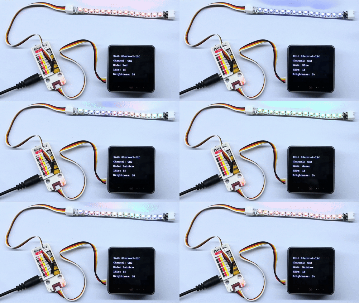
}CH2 の 15 個の RGB LED は、赤、緑、青を順に各約 200ms 点灯させます。その後、レインボーパターンが 1 個目から 15 個目の LED に向かって約 20ms ごとに更新されながらスクロールし、約 1 秒間続いた後、この動作を繰り返します。すべての色の RGB 成分は 5% にスケーリングされます。CoreS3 のディスプレイにはチャンネル、モード、LED の数、明るさ設定が表示されます。シリアルポートには赤、緑、青の単色表示中のみ、色名と明るさ設定が出力されます。
4. コンパイルと書き込み
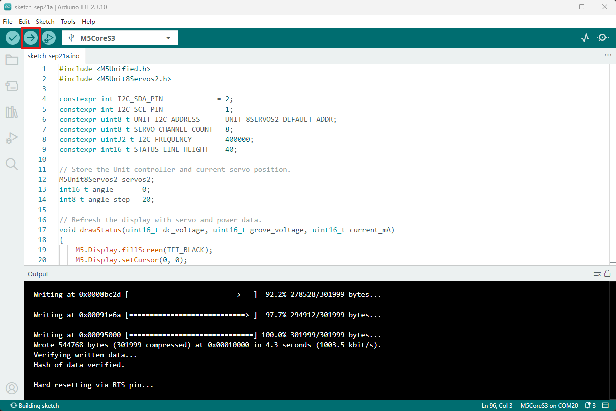
- 上記のサンプルプログラムをプロジェクトのコード領域にコピーし、デバイスポートを選択します(詳細はプログラムのコンパイルと書き込みを参照してください)。その後、Arduino IDE 左上のコンパイルと書き込みボタンをクリックし、プログラムのコンパイルとデバイスへの書き込みが完了するまで待ちます。