Arduino入門
2. デバイス&サンプル
3. M5Unified
4. M5GFX
5. 拡張モジュール&サンプル
Unit
Module
Atomic
Tab5
IoT
アクセサリー
Unit 8Servos2-Chain Arduino 使用チュートリアル
1. 準備
環境設定:Arduino IDE 入門チュートリアルを参照して IDE をインストールし、使用する開発ボードに対応するボードパッケージとドライバライブラリをインストールしてください。
使用するライブラリ:
使用するハードウェア:

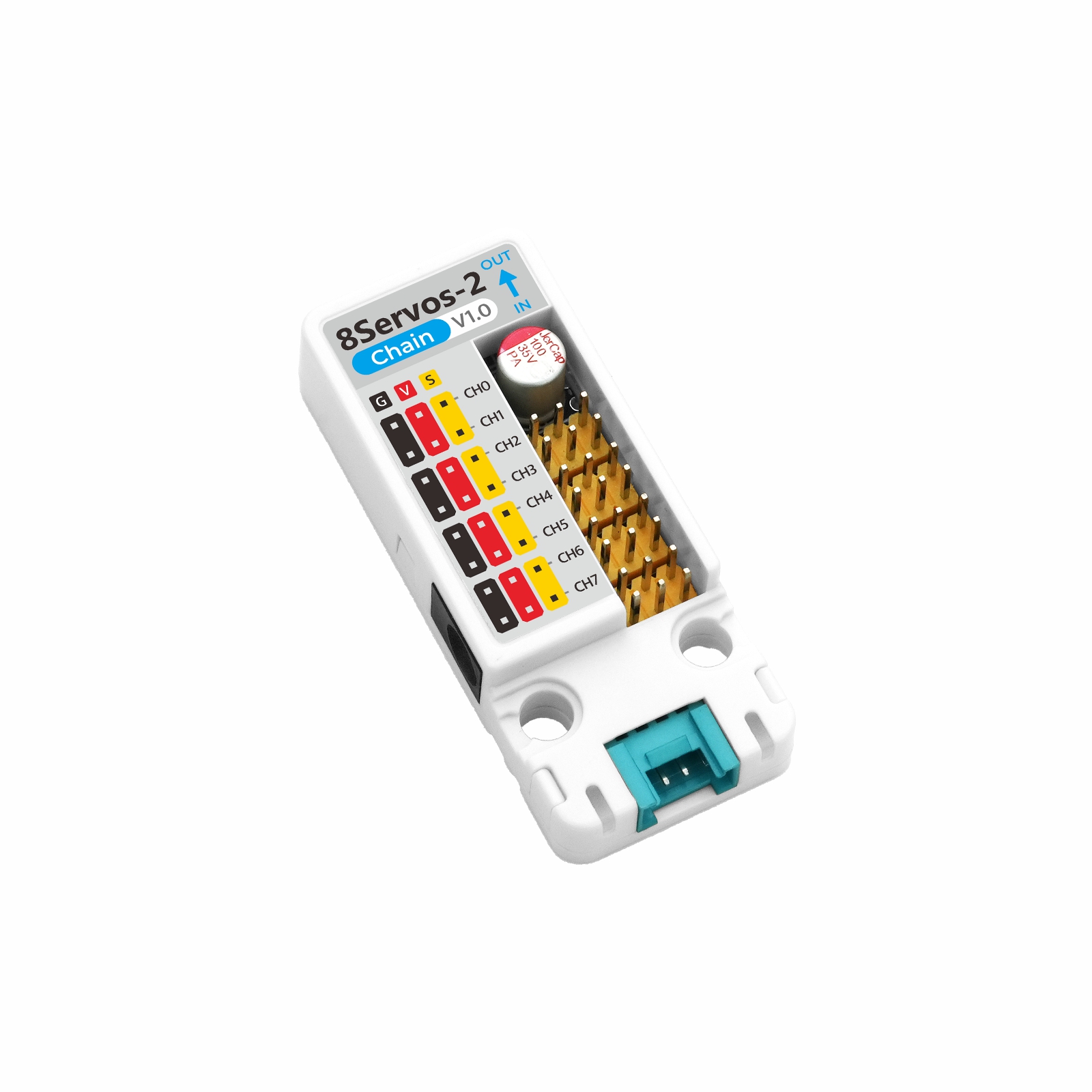
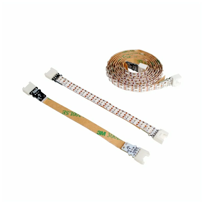
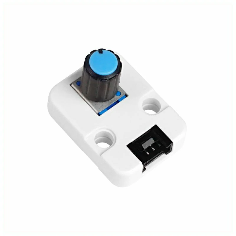
2. 注意事項
3. サンプルプログラム
- このチュートリアルでは、ホストデバイスとして CoreS3 を使用し、Unit 8Servos2-Chain でサーボを制御します。Unit 8Servos2-Chain はシリアルポートを介してホストと通信します。デバイスを接続すると、対応するピンは
G17 (TXD)とG18 (RXD)です。
setup() 内で cfg.output_power を true に設定してください。3.1 サーボ制御
#include <M5Unified.h>
#include "M5Chain.h"

#define TXD_PIN             17
#define RXD_PIN             18
#define SERVO_CHANNEL_COUNT 8
#define ANGLE_STEP          20
#define LOOP_DELAY_MS       200

// Chain state and device list.
Chain M5Chain;
device_list_t *devices_list = nullptr;
uint16_t device_nums = 0;
uint8_t operation_status = 0;
uint8_t angle = 0;
bool servo_ready = false;
M5Canvas canvas(&M5.Display);

void showMessage(const char *message)
{
    // Show a status message on the display.
    canvas.clear();
    canvas.setCursor(0, 0);
    canvas.println(message);
    canvas.pushSprite(0, 0);
}

bool updateDeviceList()
{
    // Discover all devices on the Chain bus.
    if (!M5Chain.isDeviceConnected()) {
        Serial.println("Chain device not connected");
        return false;
    }

    if (M5Chain.getDeviceNum(&device_nums) != CHAIN_OK || device_nums == 0) {
        Serial.println("Failed to get Chain device count");
        return false;
    }

    // Allocate storage for the device list returned by M5Chain.
    devices_list = (device_list_t *)malloc(sizeof(device_list_t));
    if (devices_list == nullptr) {
        Serial.println("Failed to allocate device list");
        return false;
    }

    devices_list->count = device_nums;
    devices_list->devices = (device_info_t *)malloc(sizeof(device_info_t) * device_nums);
    if (devices_list->devices == nullptr) {
        free(devices_list);
        devices_list = nullptr;
        Serial.println("Failed to allocate device information");
        return false;
    }

    if (!M5Chain.getDeviceList(devices_list)) {
        free(devices_list->devices);
        free(devices_list);
        devices_list = nullptr;
        Serial.println("Failed to get Chain device list");
        return false;
    }

    // Print the detected device IDs and types.
    Serial.printf("Chain device count: %u\r\n", devices_list->count);
    for (uint8_t i = 0; i < devices_list->count; i++) {
        Serial.printf("ID[%u], type: 0x%02X\r\n", devices_list->devices[i].id,
                      devices_list->devices[i].device_type);
    }
    return true;
}

bool initializeServoMode()
{
    if (devices_list == nullptr) {
        return false;
    }

    // Configure all eight channels as servo outputs.
    user_gpio_mode_t modes[SERVO_CHANNEL_COUNT];
    for (uint8_t i = 0; i < SERVO_CHANNEL_COUNT; i++) {
        modes[i] = USER_GPIO_SERVO_MODE;
    }

    bool found = false;
    for (uint8_t i = 0; i < devices_list->count; i++) {
        if (devices_list->devices[i].device_type != UNIT_8SERVOS2_CHAIN_TYPE_CODE) {
            continue;
        }

        found = true;
        uint8_t device_id = devices_list->devices[i].id;
        chain_status_t status = M5Chain.setServosModeAll(
            device_id, modes, SERVO_CHANNEL_COUNT, &operation_status);
        if (status != CHAIN_OK || operation_status != 1) {
            Serial.printf("ID[%u] servo mode setup failed\r\n", device_id);
            continue;
        }

        Serial.printf("ID[%u] servo mode setup success\r\n", device_id);
    }
    return found;
}

bool setAndVerifyAngle(uint8_t target_angle)
{
    if (devices_list == nullptr) {
        return false;
    }

    // Set the same target angle on every servo channel.
    uint8_t target_angles[SERVO_CHANNEL_COUNT];
    uint8_t read_angles[SERVO_CHANNEL_COUNT] = {0};
    for (uint8_t i = 0; i < SERVO_CHANNEL_COUNT; i++) {
        target_angles[i] = target_angle;
    }

    bool all_success = true;
    for (uint8_t i = 0; i < devices_list->count; i++) {
        if (devices_list->devices[i].device_type != UNIT_8SERVOS2_CHAIN_TYPE_CODE) {
            continue;
        }

        uint8_t device_id = devices_list->devices[i].id;
        chain_status_t status = M5Chain.setServosAngleAll(
            device_id, target_angles, SERVO_CHANNEL_COUNT, &operation_status);
        if (status != CHAIN_OK || operation_status != 1 ||
            M5Chain.getServosAngleAll(device_id, read_angles, SERVO_CHANNEL_COUNT) != CHAIN_OK) {
            Serial.printf("ID[%u] angle operation failed\r\n", device_id);
            all_success = false;
            continue;
        }

        // Verify every channel by reading the angle back.
        for (uint8_t channel = 0; channel < SERVO_CHANNEL_COUNT; channel++) {
            if (read_angles[channel] != target_angle) {
                Serial.printf("ID[%u] CH[%u] angle mismatch: %u / %u\r\n",
                              device_id, channel, target_angle, read_angles[channel]);
                all_success = false;
            }
        }
    }
    return all_success;
}

bool readAndDisplayPower(uint8_t current_angle)
{
    if (devices_list == nullptr) {
        return false;
    }

    // Read voltage and current telemetry from each matching device.
    bool all_success = true;
    bool display_updated = false;
    for (uint8_t i = 0; i < devices_list->count; i++) {
        if (devices_list->devices[i].device_type != UNIT_8SERVOS2_CHAIN_TYPE_CODE) {
            continue;
        }

        uint8_t device_id = devices_list->devices[i].id;
        uint16_t dc_voltage = 0;
        uint16_t grove_voltage = 0;
        uint16_t system_current = 0;
        chain_status_t dc_status = M5Chain.getServosDcVoltage(device_id, &dc_voltage);
        chain_status_t grove_status = M5Chain.getServosGroveVoltage(device_id, &grove_voltage);
        chain_status_t current_status = M5Chain.getServosSysCurrent(device_id, &system_current);

        if (dc_status != CHAIN_OK || grove_status != CHAIN_OK || current_status != CHAIN_OK) {
            Serial.printf("ID[%u] power monitor failed: DC=%d, Grove=%d, Current=%d\r\n",
                          device_id, dc_status, grove_status, current_status);
            all_success = false;
            continue;
        }

        Serial.printf("ID[%u] power: DC=%umV, Grove=%umV, Current=%umA\r\n",
                      device_id, dc_voltage, grove_voltage, system_current);

        // Display the first matching device while logging all devices.
        if (!display_updated) {
            canvas.clear();
            canvas.setCursor(0, 0);
            canvas.println("Unit 8Servos2-Chain");
            canvas.setCursor(0, 40);
            canvas.printf("Angle: %u", current_angle);
            canvas.setCursor(0, 80);
            canvas.printf("DC: %umV", dc_voltage);
            canvas.setCursor(0, 120);
            canvas.printf("Current: %umA", system_current);
            canvas.setCursor(0, 160);
            canvas.printf("Grove: %umV", grove_voltage);
            canvas.pushSprite(0, 0);
            display_updated = true;
        }
    }
    return all_success;
}

void setup()
{
    // Disable 5V output on the CoreS3 Grove port.
    auto cfg = M5.config();
    cfg.output_power = false;
    M5.begin(cfg);
    canvas.createSprite(320, 240);
    canvas.setFont(&fonts::FreeMonoBold12pt7b);
    canvas.setTextSize(1);
    Serial.begin(115200);
    Serial.println("Unit 8Servos2-Chain Test");

    // Start Chain UART communication.
    M5Chain.begin(&Serial2, 115200, RXD_PIN, TXD_PIN);
    if (!updateDeviceList()) {
        showMessage("Chain device not found");
        return;
    }

    servo_ready = initializeServoMode();
    if (!servo_ready) {
        showMessage("8Servos2-Chain not found");
        return;
    }
    showMessage("8Servos2-Chain ready");
}

void loop()
{
    if (!servo_ready) {
        delay(LOOP_DELAY_MS);
        return;
    }

    // Set the next angle and verify the response.
    if (setAndVerifyAngle(angle)) {
        Serial.printf("All servo channels set to %u degrees\r\n", angle);
    } else {
        Serial.println("Servo angle operation failed");
    }

    // Update the power monitor display and serial log.
    readAndDisplayPower(angle);

    // Advance through the 0-180 degree test range.
    angle += ANGLE_STEP;
    if (angle > 180) {
        angle = 0;
    }
    delay(LOOP_DELAY_MS);
}デバイスの電源を入れると、プログラムはシリアルモニターに Chain バス上のデバイス数、デバイス ID、デバイスタイプを出力し、Unit 8Servos2-Chain を検索します。デバイスが見つかると、すべてのチャンネルをサーボモードに設定し、0°~180°の範囲を 20°刻みでサーボ角度を繰り返し設定して、DC 入力電圧、Grove インターフェース電圧、システム総電流を読み取ります。複数の Unit 8Servos2-Chain を接続した場合、シリアルポートには各デバイスのモニタリングデータが出力され、ディスプレイには最初に検出されたデバイスのデータが表示されます。
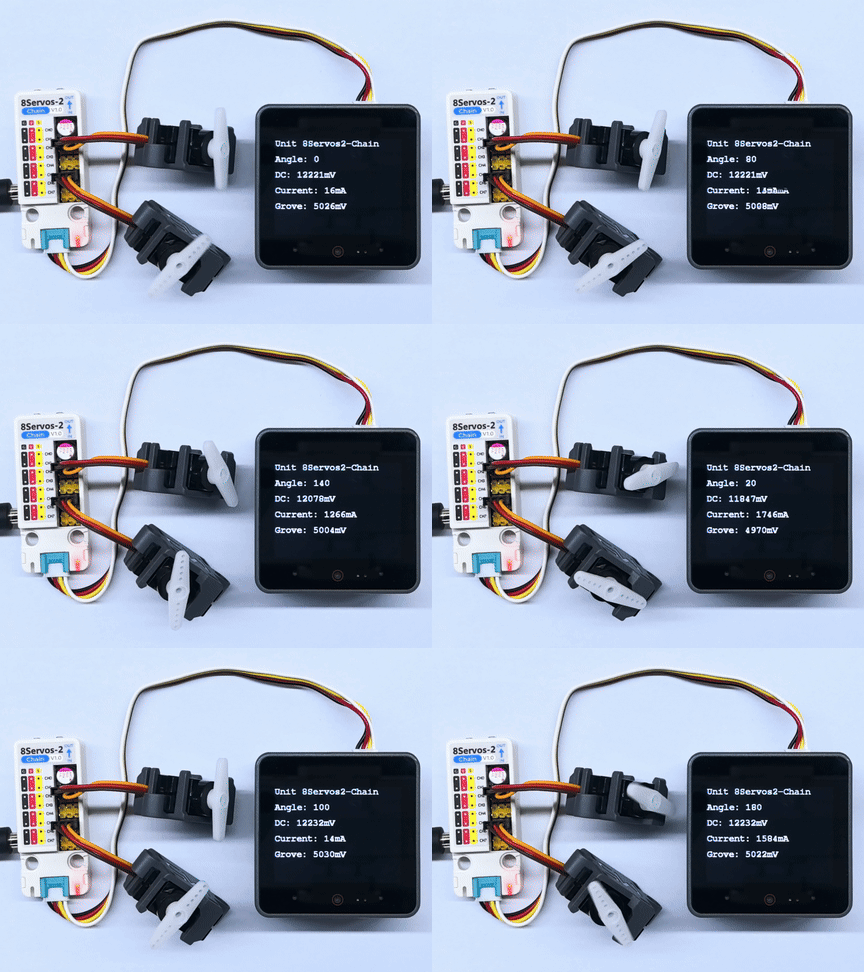
シリアル出力例:
Unit 8Servos2-Chain Test
Chain device count: 1
ID[1], type: 0x0C
ID[1] servo mode setup success
All servo channels set to 0 degrees
ID[1] power: DC=12254mV, Grove=5046mV, Current=1768mA
All servo channels set to 20 degrees
ID[1] power: DC=12254mV, Grove=5046mV, Current=12mA
All servo channels set to 40 degrees
ID[1] power: DC=12265mV, Grove=5046mV, Current=1700mA
All servo channels set to 60 degrees
ID[1] power: DC=12265mV, Grove=5044mV, Current=12mA
All servo channels set to 80 degrees
ID[1] power: DC=12265mV, Grove=5046mV, Current=1590mA
All servo channels set to 100 degrees
ID[1] power: DC=12254mV, Grove=5044mV, Current=20mA
All servo channels set to 120 degrees
ID[1] power: DC=12243mV, Grove=5008mV, Current=1522mA
All servo channels set to 140 degrees
ID[1] power: DC=12254mV, Grove=5046mV, Current=10mA
All servo channels set to 160 degrees
ID[1] power: DC=12254mV, Grove=5004mV, Current=1488mA
All servo channels set to 180 degrees
ID[1] power: DC=12265mV, Grove=5044mV, Current=12mA3.2 入出力制御
#include <M5Unified.h>
#include "M5Chain.h"

#define TXD_PIN       17
#define RXD_PIN       18
#define GPIO_COUNT    8
#define CH0           0
#define CH3           3
#define CH4           4
#define CH7           7
#define LOOP_DELAY_MS 500

// Chain state and device list.
Chain M5Chain;
device_list_t *devices_list = nullptr;
uint16_t device_nums = 0;
uint8_t operation_status = 0;
uint8_t unit_id = 0;
bool unit_ready = false;
bool output_level = false;
M5Canvas canvas(&M5.Display);

void showMessage(const char *message)
{
    // Show a status message on the display.
    canvas.clear();
    canvas.setCursor(0, 0);
    canvas.println(message);
    canvas.pushSprite(0, 0);
}

bool updateDeviceList()
{
    // Discover the Unit 8Servos2-Chain device.
    if (!M5Chain.isDeviceConnected()) {
        Serial.println("Chain device not connected");
        return false;
    }

    if (M5Chain.getDeviceNum(&device_nums) != CHAIN_OK || device_nums == 0) {
        Serial.println("Failed to get Chain device count");
        return false;
    }

    devices_list = (device_list_t *)malloc(sizeof(device_list_t));
    if (devices_list == nullptr) {
        Serial.println("Failed to allocate device list");
        return false;
    }

    devices_list->count = device_nums;
    devices_list->devices = (device_info_t *)malloc(sizeof(device_info_t) * device_nums);
    if (devices_list->devices == nullptr || !M5Chain.getDeviceList(devices_list)) {
        free(devices_list->devices);
        free(devices_list);
        devices_list = nullptr;
        Serial.println("Failed to get Chain device list");
        return false;
    }

    for (uint8_t i = 0; i < devices_list->count; i++) {
        if (devices_list->devices[i].device_type == UNIT_8SERVOS2_CHAIN_TYPE_CODE) {
            unit_id = devices_list->devices[i].id;
            break;
        }
    }
    return unit_id != 0;
}

bool configureChannels()
{
    // Configure CH0 and CH4 as outputs, and CH3 and CH7 as inputs.
    user_gpio_mode_t modes[GPIO_COUNT];
    for (uint8_t i = 0; i < GPIO_COUNT; i++) {
        modes[i] = USER_GPIO_INPUT_MODE;
    }
    modes[CH0] = USER_GPIO_OUTPUT_MODE;
    modes[CH4] = USER_GPIO_OUTPUT_MODE;

    chain_status_t status = M5Chain.setServosModeAll(
        unit_id, modes, GPIO_COUNT, &operation_status);
    if (status != CHAIN_OK || operation_status != 1) {
        return false;
    }

    if (M5Chain.setServosInputPuPd(unit_id, CH3, USER_GPIO_PULL_DOWN, &operation_status) != CHAIN_OK ||
        operation_status != 1) {
        return false;
    }
    if (M5Chain.setServosInputPuPd(unit_id, CH7, USER_GPIO_PULL_DOWN, &operation_status) != CHAIN_OK ||
        operation_status != 1) {
        return false;
    }

    return true;
}

const char *levelName(user_sys_gpio_level_t level)
{
    return level == USER_GPIO_LEVEL_HIGH ? "HIGH" : "LOW";
}

void updateOutputAndDisplay()
{
    // Set CH0 and CH4 to opposite levels at the same update step.
    user_sys_gpio_level_t ch0_level = output_level ? USER_GPIO_LEVEL_HIGH : USER_GPIO_LEVEL_LOW;
    user_sys_gpio_level_t ch4_level = output_level ? USER_GPIO_LEVEL_LOW : USER_GPIO_LEVEL_HIGH;
    bool output_success =
        M5Chain.setServosOutputLevel(unit_id, CH0, ch0_level, &operation_status) == CHAIN_OK &&
        operation_status == 1;
    output_success =
        M5Chain.setServosOutputLevel(unit_id, CH4, ch4_level, &operation_status) == CHAIN_OK &&
        operation_status == 1 && output_success;

    user_sys_gpio_level_t ch3_level = USER_GPIO_LEVEL_LOW;
    user_sys_gpio_level_t ch7_level = USER_GPIO_LEVEL_LOW;
    bool input_success =
        M5Chain.getServosInputLevel(unit_id, CH3, &ch3_level, &operation_status) == CHAIN_OK &&
        operation_status == 1;
    input_success =
        M5Chain.getServosInputLevel(unit_id, CH7, &ch7_level, &operation_status) == CHAIN_OK &&
        operation_status == 1 && input_success;

    canvas.clear();
    canvas.setCursor(0, 0);
    canvas.println("Unit 8Servos2-Chain");
    canvas.setCursor(0, 40);
    canvas.printf("CH0 OUT: %s", levelName(ch0_level));
    canvas.setCursor(0, 80);
    canvas.printf("CH4 OUT: %s", levelName(ch4_level));
    canvas.setCursor(0, 120);
    canvas.printf("CH3 IN:  %s", input_success ? levelName(ch3_level) : "ERROR");
    canvas.setCursor(0, 160);
    canvas.printf("CH7 IN:  %s", input_success ? levelName(ch7_level) : "ERROR");
    canvas.pushSprite(0, 0);

    Serial.printf("CH0=%s, CH4=%s, CH3=%s, CH7=%s\r\n",
                  output_success ? levelName(ch0_level) : "ERROR",
                  output_success ? levelName(ch4_level) : "ERROR",
                  input_success ? levelName(ch3_level) : "ERROR",
                  input_success ? levelName(ch7_level) : "ERROR");
    output_level = !output_level;
}

void setup()
{
    // Disable 5V output on the CoreS3 Grove port.
    auto cfg = M5.config();
    cfg.output_power = false;
    M5.begin(cfg);
    canvas.createSprite(320, 240);
    canvas.setFont(&fonts::FreeMonoBold12pt7b);
    canvas.setTextSize(1);
    Serial.begin(115200);
    Serial.println("Unit 8Servos2-Chain GPIO Test");

    // Start Chain UART communication.
    M5Chain.begin(&Serial2, 115200, RXD_PIN, TXD_PIN);
    if (!updateDeviceList() || !configureChannels()) {
        showMessage("GPIO setup failed");
        return;
    }
    unit_ready = true;
    showMessage("GPIO test ready");
}

void loop()
{
    if (!unit_ready) {
        delay(LOOP_DELAY_MS);
        return;
    }

    updateOutputAndDisplay();
    delay(LOOP_DELAY_MS);
}
デバイスの電源を入れると、プログラムはシリアルモニターに Chain バス上のデバイス数、デバイス ID、デバイスタイプを出力し、Unit 8Servos2-Chain を検索します。デバイスが見つかると、CH0 と CH4 を出力モード、CH3 と CH7 を入力モードに設定し、入力のプルダウン抵抗を有効にします。500ms ごとに CH0 と CH4 の出力を互いに逆の論理レベルに切り替え、CH3 と CH7 の入力レベルを読み取ります。ディスプレイには現在の出力と入力の状態が表示され、シリアルポートにも同じデータが出力されます。
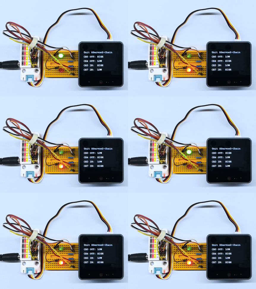
3.3 ADC 測定
#include <M5Unified.h>
#include "M5Chain.h"

#define TXD_PIN       17
#define RXD_PIN       18
#define GPIO_COUNT    8
#define ADC_CHANNEL   4
#define LOOP_DELAY_MS 100

// Chain state and device list.
Chain M5Chain;
device_list_t *devices_list = nullptr;
uint16_t device_nums = 0;
uint8_t operation_status = 0;
uint8_t unit_id = 0;
bool unit_ready = false;
M5Canvas canvas(&M5.Display);

void showMessage(const char *message)
{
    // Show a status message on the display.
    canvas.clear();
    canvas.setCursor(0, 0);
    canvas.println(message);
    canvas.pushSprite(0, 0);
}

bool updateDeviceList()
{
    // Discover the Unit 8Servos2-Chain device.
    if (!M5Chain.isDeviceConnected()) {
        Serial.println("Chain device not connected");
        return false;
    }

    if (M5Chain.getDeviceNum(&device_nums) != CHAIN_OK || device_nums == 0) {
        Serial.println("Failed to get Chain device count");
        return false;
    }

    devices_list = (device_list_t *)malloc(sizeof(device_list_t));
    if (devices_list == nullptr) {
        Serial.println("Failed to allocate device list");
        return false;
    }

    devices_list->count = device_nums;
    devices_list->devices = (device_info_t *)malloc(sizeof(device_info_t) * device_nums);
    if (devices_list->devices == nullptr || !M5Chain.getDeviceList(devices_list)) {
        free(devices_list->devices);
        free(devices_list);
        devices_list = nullptr;
        Serial.println("Failed to get Chain device list");
        return false;
    }

    for (uint8_t i = 0; i < devices_list->count; i++) {
        if (devices_list->devices[i].device_type == UNIT_8SERVOS2_CHAIN_TYPE_CODE) {
            unit_id = devices_list->devices[i].id;
            break;
        }
    }
    return unit_id != 0;
}

bool configureAdc()
{
    // Configure CH4 for ADC and keep the other channels as digital inputs.
    user_gpio_mode_t modes[GPIO_COUNT];
    for (uint8_t i = 0; i < GPIO_COUNT; i++) {
        modes[i] = USER_GPIO_INPUT_MODE;
    }
    modes[ADC_CHANNEL] = USER_GPIO_ADC_MODE;

    chain_status_t status = M5Chain.setServosModeAll(
        unit_id, modes, GPIO_COUNT, &operation_status);
    return status == CHAIN_OK && operation_status == 1;
}

void readAndDisplayAdc()
{
    // Read the CH4 ADC value continuously.
    uint16_t adc_value = 0;
    bool success = M5Chain.getServosAdcValue(
                       unit_id, ADC_CHANNEL, &adc_value, &operation_status) == CHAIN_OK &&
                   operation_status == 1;

    canvas.clear();
    canvas.setCursor(0, 0);
    canvas.println("Unit 8Servos2-Chain");
    canvas.setCursor(0, 40);
    canvas.println("ADC monitor");
    canvas.setCursor(0, 80);
    canvas.printf("CH4: %s", success ? "READY" : "ERROR");
    canvas.setCursor(0, 120);
    canvas.printf("Value: %u", adc_value);
    canvas.pushSprite(0, 0);

    Serial.printf("CH4 ADC: %s, value=%u\r\n", success ? "OK" : "ERROR", adc_value);
}

void setup()
{
    // Disable 5V output on the CoreS3 Grove port.
    auto cfg = M5.config();
    cfg.output_power = false;
    M5.begin(cfg);
    canvas.createSprite(320, 240);
    canvas.setFont(&fonts::FreeMonoBold12pt7b);
    canvas.setTextSize(1);
    Serial.begin(115200);
    Serial.println("Unit 8Servos2-Chain ADC Test");

    // Start Chain UART communication.
    M5Chain.begin(&Serial2, 115200, RXD_PIN, TXD_PIN);
    if (!updateDeviceList() || !configureAdc()) {
        showMessage("ADC setup failed");
        return;
    }
    unit_ready = true;
    showMessage("ADC test ready");
}

void loop()
{
    if (!unit_ready) {
        delay(LOOP_DELAY_MS);
        return;
    }

    readAndDisplayAdc();
    delay(LOOP_DELAY_MS);
}
起動後、プログラムは CH4 を ADC モードに設定し、CH4 の ADC 生データを継続的に読み取ります。CoreS3 のディスプレイには現在のチャンネルと ADC 値が表示され、シリアルポートには測定状態と結果が出力されます。プログラムは 100ms ごとに更新します。
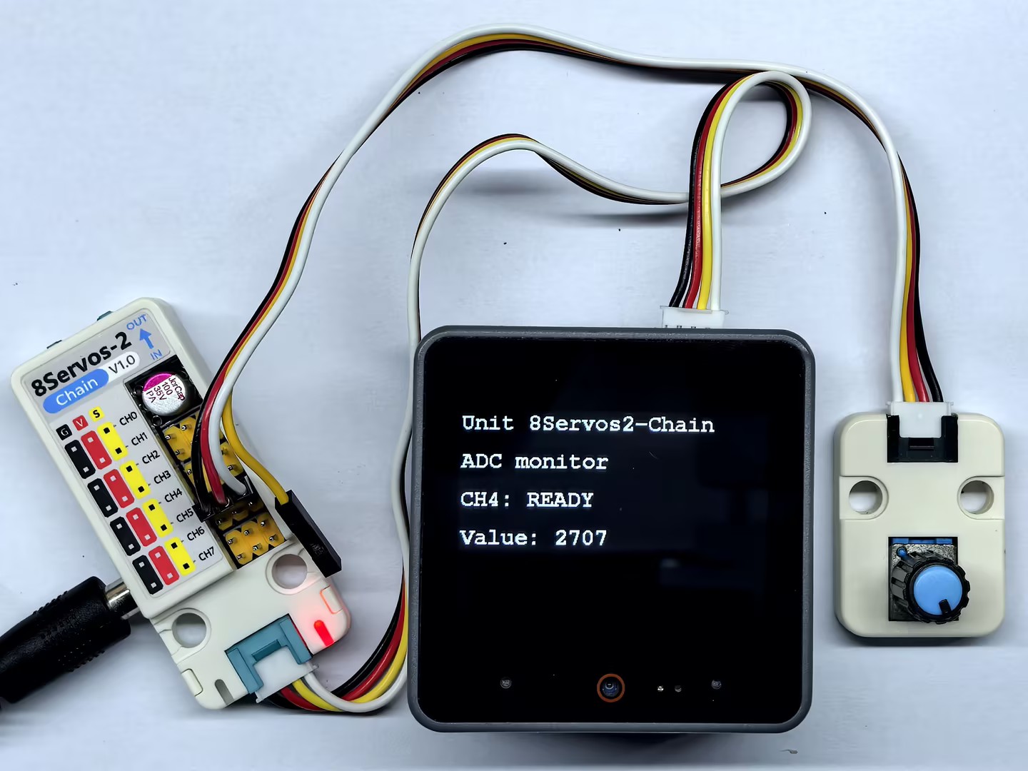
3.4 PWM 出力
#include <M5Unified.h>
#include "M5Chain.h"

#define TXD_PIN       17
#define RXD_PIN       18
#define GPIO_COUNT    8
#define CH0           0
#define CH4           4
#define PWM_MAX_DUTY  100
#define DUTY_STEP     10
#define LOOP_DELAY_MS 50

// Chain state and device list.
Chain M5Chain;
device_list_t *devices_list = nullptr;
uint16_t device_nums = 0;
uint8_t operation_status = 0;
uint8_t unit_id = 0;
bool unit_ready = false;
uint8_t ch0_duty = 0;
uint8_t ch4_duty = PWM_MAX_DUTY;
bool duty_increasing = true;
M5Canvas canvas(&M5.Display);

void showMessage(const char *message)
{
    // Show a status message on the display.
    canvas.clear();
    canvas.setCursor(0, 0);
    canvas.println(message);
    canvas.pushSprite(0, 0);
}

bool updateDeviceList()
{
    // Discover the Unit 8Servos2-Chain device.
    if (!M5Chain.isDeviceConnected()) {
        Serial.println("Chain device not connected");
        return false;
    }

    if (M5Chain.getDeviceNum(&device_nums) != CHAIN_OK || device_nums == 0) {
        Serial.println("Failed to get Chain device count");
        return false;
    }

    devices_list = (device_list_t *)malloc(sizeof(device_list_t));
    if (devices_list == nullptr) {
        Serial.println("Failed to allocate device list");
        return false;
    }

    devices_list->count = device_nums;
    devices_list->devices = (device_info_t *)malloc(sizeof(device_info_t) * device_nums);
    if (devices_list->devices == nullptr || !M5Chain.getDeviceList(devices_list)) {
        free(devices_list->devices);
        free(devices_list);
        devices_list = nullptr;
        Serial.println("Failed to get Chain device list");
        return false;
    }

    for (uint8_t i = 0; i < devices_list->count; i++) {
        if (devices_list->devices[i].device_type == UNIT_8SERVOS2_CHAIN_TYPE_CODE) {
            unit_id = devices_list->devices[i].id;
            break;
        }
    }
    return unit_id != 0;
}

bool configurePwm()
{
    // Configure CH0 and CH4 for PWM output.
    user_gpio_mode_t modes[GPIO_COUNT];
    for (uint8_t i = 0; i < GPIO_COUNT; i++) {
        modes[i] = USER_GPIO_INPUT_MODE;
    }
    modes[CH0] = USER_GPIO_PWM_MODE;
    modes[CH4] = USER_GPIO_PWM_MODE;

    chain_status_t status = M5Chain.setServosModeAll(
        unit_id, modes, GPIO_COUNT, &operation_status);
    return status == CHAIN_OK && operation_status == 1;
}

void updatePwmAndDisplay()
{
    // Change one duty cycle up and the other down every 200 ms.
    if (duty_increasing) {
        if (ch0_duty <= PWM_MAX_DUTY - DUTY_STEP) {
            ch0_duty += DUTY_STEP;
        } else {
            ch0_duty = PWM_MAX_DUTY;
        }
        if (ch4_duty >= DUTY_STEP) {
            ch4_duty -= DUTY_STEP;
        } else {
            ch4_duty = 0;
        }
        if (ch0_duty == PWM_MAX_DUTY || ch4_duty == 0) {
            duty_increasing = false;
        }
    } else {
        if (ch0_duty >= DUTY_STEP) {
            ch0_duty -= DUTY_STEP;
        } else {
            ch0_duty = 0;
        }
        if (ch4_duty <= PWM_MAX_DUTY - DUTY_STEP) {
            ch4_duty += DUTY_STEP;
        } else {
            ch4_duty = PWM_MAX_DUTY;
        }
        if (ch0_duty == 0 || ch4_duty == PWM_MAX_DUTY) {
            duty_increasing = true;
        }
    }

    bool ch0_success =
        M5Chain.setServosPwmDuty(unit_id, CH0, ch0_duty, &operation_status) == CHAIN_OK &&
        operation_status == 1;
    bool ch4_success =
        M5Chain.setServosPwmDuty(unit_id, CH4, ch4_duty, &operation_status) == CHAIN_OK &&
        operation_status == 1;

    canvas.clear();
    canvas.setCursor(0, 0);
    canvas.println("Unit 8Servos2-Chain");
    canvas.setCursor(0, 40);
    canvas.println("PWM output");
    canvas.setCursor(0, 80);
    canvas.printf("CH0: %3u%% %s", ch0_duty, ch0_success ? "OK" : "ERR");
    canvas.setCursor(0, 120);
    canvas.printf("CH4: %3u%% %s", ch4_duty, ch4_success ? "OK" : "ERR");
    canvas.setCursor(0, 160);
    canvas.printf("Direction: %s", duty_increasing ? "UP" : "DOWN");
    canvas.pushSprite(0, 0);

    Serial.printf("PWM CH0=%u (%s), CH4=%u (%s), direction=%s\r\n",
                  ch0_duty, ch0_success ? "OK" : "ERROR",
                  ch4_duty, ch4_success ? "OK" : "ERROR",
                  duty_increasing ? "UP" : "DOWN");
}

void setup()
{
    // Disable 5V output on the CoreS3 Grove port.
    auto cfg = M5.config();
    cfg.output_power = false;
    M5.begin(cfg);
    canvas.createSprite(320, 240);
    canvas.setFont(&fonts::FreeMonoBold12pt7b);
    canvas.setTextSize(1);
    Serial.begin(115200);
    Serial.println("Unit 8Servos2-Chain PWM Test");

    // Start Chain UART communication.
    M5Chain.begin(&Serial2, 115200, RXD_PIN, TXD_PIN);
    if (!updateDeviceList() || !configurePwm()) {
        showMessage("PWM setup failed");
        return;
    }
    unit_ready = true;
    showMessage("PWM test ready");
}

void loop()
{
    if (!unit_ready) {
        delay(LOOP_DELAY_MS);
        return;
    }

    updatePwmAndDisplay();
    delay(LOOP_DELAY_MS);
}
起動後、プログラムは CH0 と CH4 を PWM 出力モードに設定します。50ms ごとにデューティ比を調整し、CH0 を増加させると同時に CH4 を減少させ、0% または 100% に達すると増減の方向を反転します。CoreS3 のディスプレイとシリアル出力には、両チャンネルの現在のデューティ比と増減の方向が表示されます。
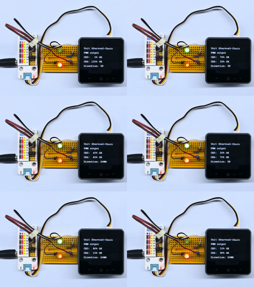
3.5 RGB LED 制御
#include <M5Unified.h>
#include "M5Chain.h"

#define TXD_PIN        17
#define RXD_PIN        18
#define GPIO_COUNT     8
#define RGB_CHANNEL    2
#define RGB_LED_COUNT  15
#define RGB_BUFFER_COUNT 16
#define RAINBOW_DURATION_MS 1000
#define RAINBOW_DELAY_MS    20

// Chain state and device list.
Chain M5Chain;
device_list_t *devices_list = nullptr;
uint16_t device_nums = 0;
uint8_t operation_status = 0;
uint8_t unit_id = 0;
bool unit_ready = false;
M5Canvas canvas(&M5.Display);

void showMessage(const char *message)
{
    // Show a status message on the display.
    canvas.clear();
    canvas.setCursor(0, 0);
    canvas.println(message);
    canvas.pushSprite(0, 0);
}

bool updateDeviceList()
{
    // Discover the Unit 8Servos2-Chain device.
    if (!M5Chain.isDeviceConnected()) {
        Serial.println("Chain device not connected");
        return false;
    }

    if (M5Chain.getDeviceNum(&device_nums) != CHAIN_OK || device_nums == 0) {
        Serial.println("Failed to get Chain device count");
        return false;
    }

    devices_list = (device_list_t *)malloc(sizeof(device_list_t));
    if (devices_list == nullptr) {
        Serial.println("Failed to allocate device list");
        return false;
    }

    devices_list->count = device_nums;
    devices_list->devices = (device_info_t *)malloc(sizeof(device_info_t) * device_nums);
    if (devices_list->devices == nullptr || !M5Chain.getDeviceList(devices_list)) {
        free(devices_list->devices);
        free(devices_list);
        devices_list = nullptr;
        Serial.println("Failed to get Chain device list");
        return false;
    }

    for (uint8_t i = 0; i < devices_list->count; i++) {
        if (devices_list->devices[i].device_type == UNIT_8SERVOS2_CHAIN_TYPE_CODE) {
            unit_id = devices_list->devices[i].id;
            break;
        }
    }
    return unit_id != 0;
}

bool configureRgb()
{
    // Configure CH2 as an RGB strip control channel.
    user_gpio_mode_t modes[GPIO_COUNT];
    for (uint8_t i = 0; i < GPIO_COUNT; i++) {
        modes[i] = USER_GPIO_INPUT_MODE;
    }
    modes[RGB_CHANNEL] = USER_GPIO_RGB_MODE;

    chain_status_t status = M5Chain.setServosModeAll(
        unit_id, modes, GPIO_COUNT, &operation_status);
    if (status != CHAIN_OK || operation_status != 1) {
        return false;
    }

    return true;
}

uint32_t wheel(uint8_t position)
{
    // Convert a position on the color wheel to 0xRRGGBB.
    position = 255 - position;
    if (position < 85) {
        return ((uint32_t)(255 - position * 3) << 16) |
               ((uint32_t)(position * 3) << 8);
    }
    if (position < 170) {
        position -= 85;
        return ((uint32_t)(position * 3) << 16) |
               (uint32_t)(255 - position * 3);
    }
    position -= 170;
    return ((uint32_t)(255 - position * 3) << 8) |
           (uint32_t)(position * 3);
}

bool setStripColor(uint32_t color, const char *name)
{
    // Set one color on every LED in the strip.
    // M5Chain requires a 16-entry RGB buffer; the last entry is unused.
    uint32_t colors[RGB_BUFFER_COUNT] = {0};
    for (uint8_t i = 0; i < RGB_LED_COUNT; i++) {
        colors[i] = color;
    }
    bool success = M5Chain.setServosRGBBufferAll(unit_id, colors, RGB_BUFFER_COUNT) == CHAIN_OK;
    uint8_t rgb_config = 0x20 | RGB_LED_COUNT;
    success = M5Chain.setServosRGBConfig(unit_id, RGB_CHANNEL, rgb_config, &operation_status) == CHAIN_OK &&
              operation_status == 1 && success;

    canvas.clear();
    canvas.setCursor(0, 0);
    canvas.println("Unit 8Servos2-Chain");
    canvas.setCursor(0, 40);
    canvas.println("RGB strip");
    canvas.setCursor(0, 80);
    canvas.printf("Color: %s", success ? name : "ERROR");
    canvas.setCursor(0, 120);
    canvas.printf("CH2 LEDs: %u", RGB_LED_COUNT);
    canvas.pushSprite(0, 0);
    Serial.printf("RGB %s: %s\r\n", name, success ? "OK" : "ERROR");
    return success;
}

bool setRainbowStep(uint8_t step)
{
    // Shift the rainbow pattern across the strip.
    // M5Chain requires a 16-entry RGB buffer; the last entry is unused.
    uint32_t colors[RGB_BUFFER_COUNT] = {0};
    for (uint8_t i = 0; i < RGB_LED_COUNT; i++) {
        uint8_t position = (uint8_t)((uint16_t)i * 256 / RGB_LED_COUNT - step * 26);
        colors[i] = wheel(position);
    }
    bool success = M5Chain.setServosRGBBufferAll(unit_id, colors, RGB_BUFFER_COUNT) == CHAIN_OK;
    uint8_t rgb_config = 0x20 | RGB_LED_COUNT;
    success = M5Chain.setServosRGBConfig(unit_id, RGB_CHANNEL, rgb_config, &operation_status) == CHAIN_OK &&
              operation_status == 1 && success;

    canvas.clear();
    canvas.setCursor(0, 0);
    canvas.println("Unit 8Servos2-Chain");
    canvas.setCursor(0, 40);
    canvas.println("RGB strip");
    canvas.setCursor(0, 80);
    canvas.printf("Color: %s", success ? "RAINBOW" : "ERROR");
    canvas.setCursor(0, 120);
    canvas.printf("Step: %u", step);
    canvas.pushSprite(0, 0);
    return success;
}

void setup()
{
    // Disable 5V output on the CoreS3 Grove port.
    auto cfg = M5.config();
    cfg.output_power = false;
    M5.begin(cfg);
    canvas.createSprite(320, 240);
    canvas.setFont(&fonts::FreeMonoBold12pt7b);
    canvas.setTextSize(1);
    Serial.begin(115200);
    Serial.println("Unit 8Servos2-Chain RGB Test");

    // Start Chain UART communication.
    M5Chain.begin(&Serial2, 115200, RXD_PIN, TXD_PIN);
    if (!updateDeviceList() || !configureRgb()) {
        showMessage("RGB setup failed");
        return;
    }
    unit_ready = true;
    showMessage("RGB test ready");
}

void loop()
{
    if (!unit_ready) {
        delay(RAINBOW_DELAY_MS);
        return;
    }

    setStripColor(0xFF0000, "RED");
    delay(500);
    setStripColor(0x00FF00, "GREEN");
    delay(500);
    setStripColor(0x0000FF, "BLUE");
    delay(500);

    // Run a fast rainbow animation continuously for one second.
    uint32_t rainbow_start = millis();
    uint8_t step = 0;
    while (millis() - rainbow_start < RAINBOW_DURATION_MS) {
        setRainbowStep(step++);
        delay(RAINBOW_DELAY_MS);
    }
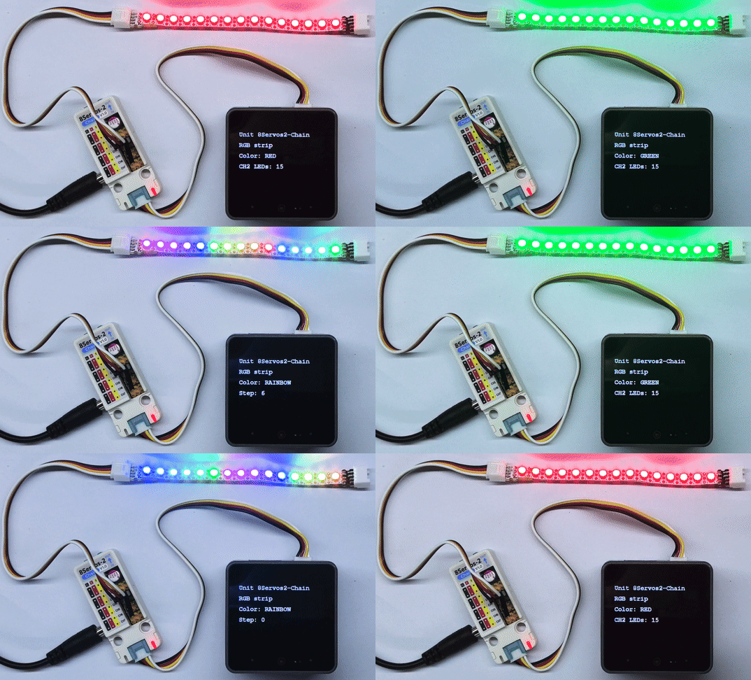
}起動後、プログラムは CH2 を RGB LED テープの制御チャンネルに設定し、RGB LED の数を 15 個に設定します。LED テープは赤、緑、青を順に各 500ms 点灯させた後、レインボーパターンを高速で連続スクロールさせます。レインボーアニメーションは 1 秒間続きます。CoreS3 のディスプレイには現在の色と、LED の数またはレインボースクロールのステップ数が表示されます。シリアルポートには赤、緑、青の単色設定の結果が出力され、レインボーのスクロール状態はディスプレイに表示されます。
4. コンパイルと書き込み
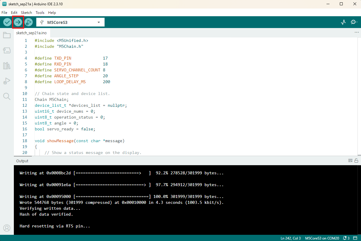
- 上記のサンプルプログラムをプロジェクトのコード欄にコピーして貼り付け、デバイスのポートを選択します(詳細はプログラムのコンパイルと書き込みを参照してください)。Arduino IDE の左上にあるコンパイルと書き込みボタンをクリックし、プログラムのコンパイルとデバイスへの書き込みが完了するまで待ちます。