

Arduino 上手教程
2. 设备开发 & 案例程序
3. M5Unified
4. M5GFX
5. 扩展模块
Unit
Module
Atomic
Tab5
IoT
Unit PoE-P4 显示输出
Unit PoE-P4 搭配 AddOn Display Out For PoE-P4 的显示输出示例程序。
注意事项
此功能需要配合
AddOn Display Out For PoE-P4 模组使用。请先确认 24P FPC 排线连接正确,再将模块的 HDMI 接口连接至外部显示器。当前驱动仅支持 1280 x 720@60Hz 与 1920 x 1080@30Hz 两种输出时序。案例程序
编译要求
- M5Stack 板管理版本 >= 3.2.6
- 开发板选项 = M5UnitPoEP4
- M5Unified 库版本 >= 0.2.17
- M5GFX 库版本 >= 0.2.24
说明
1.
2. 下方例程使用的屏幕时序为
M5UnitPoEP4HDMI 驱动已包含在 M5GFX 中,无需单独安装。2. 下方例程使用的屏幕时序为
1280 x 720@60Hz。使用 M5GFX API 绘制显示
cpp
1 2 3 4 5 6 7 8 9 10 11 12 13 14 15 16 17 18 19 20 21 22 23 24 25 26 27 28 29 30 31 32 33 34 35 36 37 38 39 40 41 42 43 44 45 46 47 48 49 50 51 52 53 54 55 56 57 58 59 60 61 62 63 64 65 66 67 68 69 70 71 72 73 74 75 76 77 78 79 80 81 82 83 84 85 86 87 88 89 90 91 92 93 94 95 96 97 98 99 100 101 102 103 104 105 106 107 108
#include <M5GFX.h>
#include <M5UnitPoEP4HDMI.h>

namespace
{
M5UnitPoEP4HDMI::config_t makeDisplayConfig()
{
  M5UnitPoEP4HDMI::config_t cfg;
  // Unit PoE-P4 HDMI only supports 1280x720@60 or 1920x1080@30.
  // Set one of the supported timings explicitly here.
  cfg.width = 1280;
  cfg.height = 720;
  cfg.refresh_rate = 60;

  // Switch to 1080p30 by uncommenting the three lines below.
  // cfg.width = 1920;
  // cfg.height = 1080;
  // cfg.refresh_rate = 30;
  return cfg;
}
}

// Start the display with the selected HDMI timing.
M5UnitPoEP4HDMI display(makeDisplayConfig());

static constexpr size_t BAR_COUNT = 64;
static int max_y[BAR_COUNT];
static int prev_y[BAR_COUNT];
static uint32_t colors[BAR_COUNT];

void setup(void)
{
  display.init();
  display.startWrite();
  display.fillScreen(TFT_BLACK);

  if (display.isEPD())
  {
    display.setEpdMode(epd_mode_t::epd_fastest);
  }
  if (display.width() < display.height())
  {
    display.setRotation(display.getRotation() ^ 1);
  }

  for (int x = 0; x < BAR_COUNT; ++x)
  {
    prev_y[x] = display.height();
    max_y[x] = display.height();
    int r=0,g=0,b=0;
    switch (x >> 4)
    {
      case 0:
        b = 255;
        g = x*0x11;
        break;
      case 1:
        b = 255 - (x&15)*0x11;
        g = 255;
        break;
      case 2:
        g = 255;
        r = (x&15)*0x11;
        break;
      case 3:
        r = 255;
        g = 255 - (x&15)*0x11;
        break;
    }
    colors[x] = display.color888(r,g,b);
  }
}

void loop(void)
{
  int h = display.height();

  static int i;
  ++i;
  display.waitDisplay();
  for (int x = 0; x < BAR_COUNT; ++x)
  {
    int y = (h>>1) - (sinf((float)((x-24)*i) / 3210.0f) + sinf((float)((x-40)*i) / 1234.0f)) * (h>>2);

    int xpos = x * display.width() / BAR_COUNT;
    int w = ((x+1) * display.width() / BAR_COUNT) - xpos - 1;
    if (max_y[x]+1 >= y) { max_y[x] = y-1; }
    else
    {
      if ((i & 3) ==0 )
      {
        display.fillRect(xpos, max_y[x]-3, w, 1, TFT_BLACK);
        max_y[x]++;
      }
    }
    display.fillRect(xpos, max_y[x]-3, w, 3, TFT_WHITE);
    if (prev_y[x] < y)
    {
      display.fillRect(xpos, prev_y[x], w, y - prev_y[x], TFT_BLACK);
    }
    else
    {
      display.fillRect(xpos, y, w, prev_y[x] - y, colors[x]);
    }
    prev_y[x] = y;
  }
  display.display();
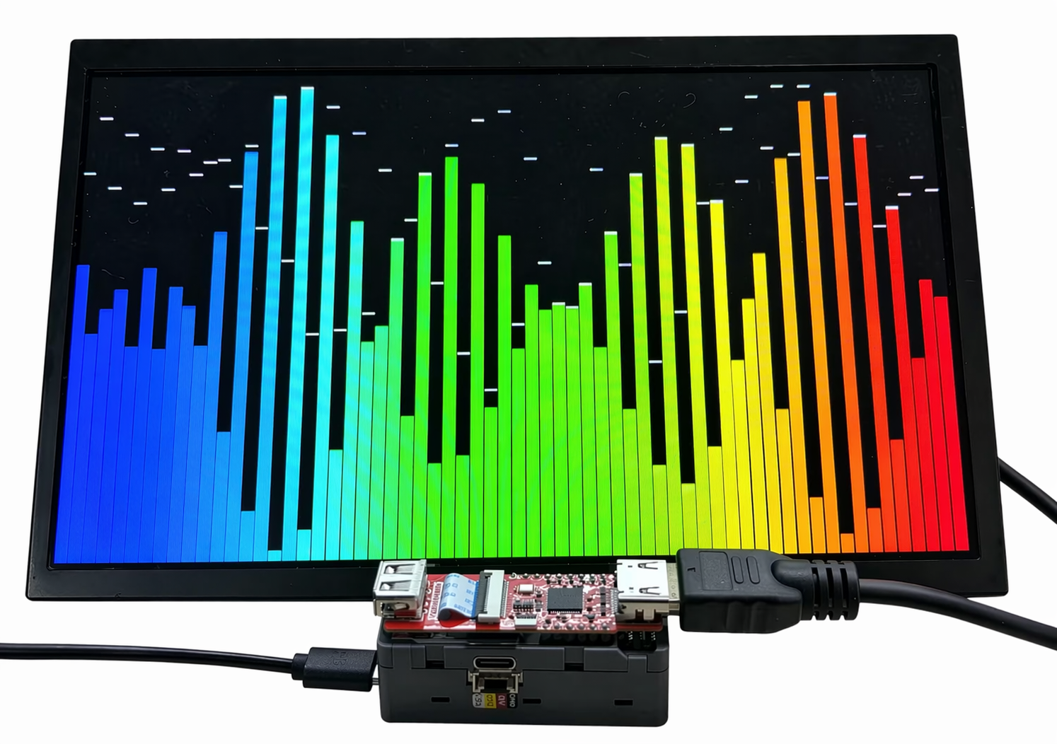
}该程序会初始化 AddOn Display Out For PoE-P4 的 HDMI 显示输出,并在外接显示器上绘制动态彩色波形条图。
显示 SD 卡中图片
cpp
1 2 3 4 5 6 7 8 9 10 11 12 13 14 15 16 17 18 19 20 21 22 23 24 25 26 27 28 29 30 31 32 33 34 35 36 37 38 39 40 41 42 43 44 45 46 47 48 49 50 51 52 53 54 55 56 57 58 59 60 61 62 63 64 65
#include "FS.h"
#include "SD_MMC.h"
#include <M5Unified.h>
#include <M5GFX.h>
#include <M5UnitPoEP4HDMI.h>

namespace
{
M5UnitPoEP4HDMI::config_t makeDisplayConfig()
{
  M5UnitPoEP4HDMI::config_t cfg;
  // Unit PoE-P4 HDMI only supports 1280x720@60 or 1920x1080@30.
  // Set one of the supported timings explicitly here.
  cfg.width = 1280;
  cfg.height = 720;
  cfg.refresh_rate = 60;

  // Switch to 1080p30 by uncommenting the three lines below.
  // cfg.width = 1920;
  // cfg.height = 1080;
  // cfg.refresh_rate = 30;
  return cfg;
}
}

// Start the display with the selected HDMI timing.
M5UnitPoEP4HDMI display(makeDisplayConfig());

void setup()
{
    Serial.begin(115200);

    display.begin();

    if (display.width() < display.height()) {
        display.setRotation(display.getRotation() ^ 1);
    }

    if (!SD_MMC.setPins(SDMMC_CLK, SDMMC_CMD, SDMMC_D0, SDMMC_D1, SDMMC_D2, SDMMC_D3)) {
        Serial.println("SD_MMC pin change failed");
        return;
    }

    if (!SD_MMC.begin()) {
        Serial.println("SD_MMC begin failed");
        return;
    }

    Serial.println("SD_MMC begin success");

    uint8_t cardType = SD_MMC.cardType();
    if (cardType == CARD_NONE) {
        Serial.println("No SD card");
        return;
    }

    Serial.printf("Card size: %llu MB\n", SD_MMC.cardSize() / 1024 / 1024);

    display.drawJpgFile(SD_MMC, "/U221_AddOn_Display_Out_For_PoE-P4_Arduino_test_picture.jpg", 0, 0);
}

void loop()
{
    delay(1000);
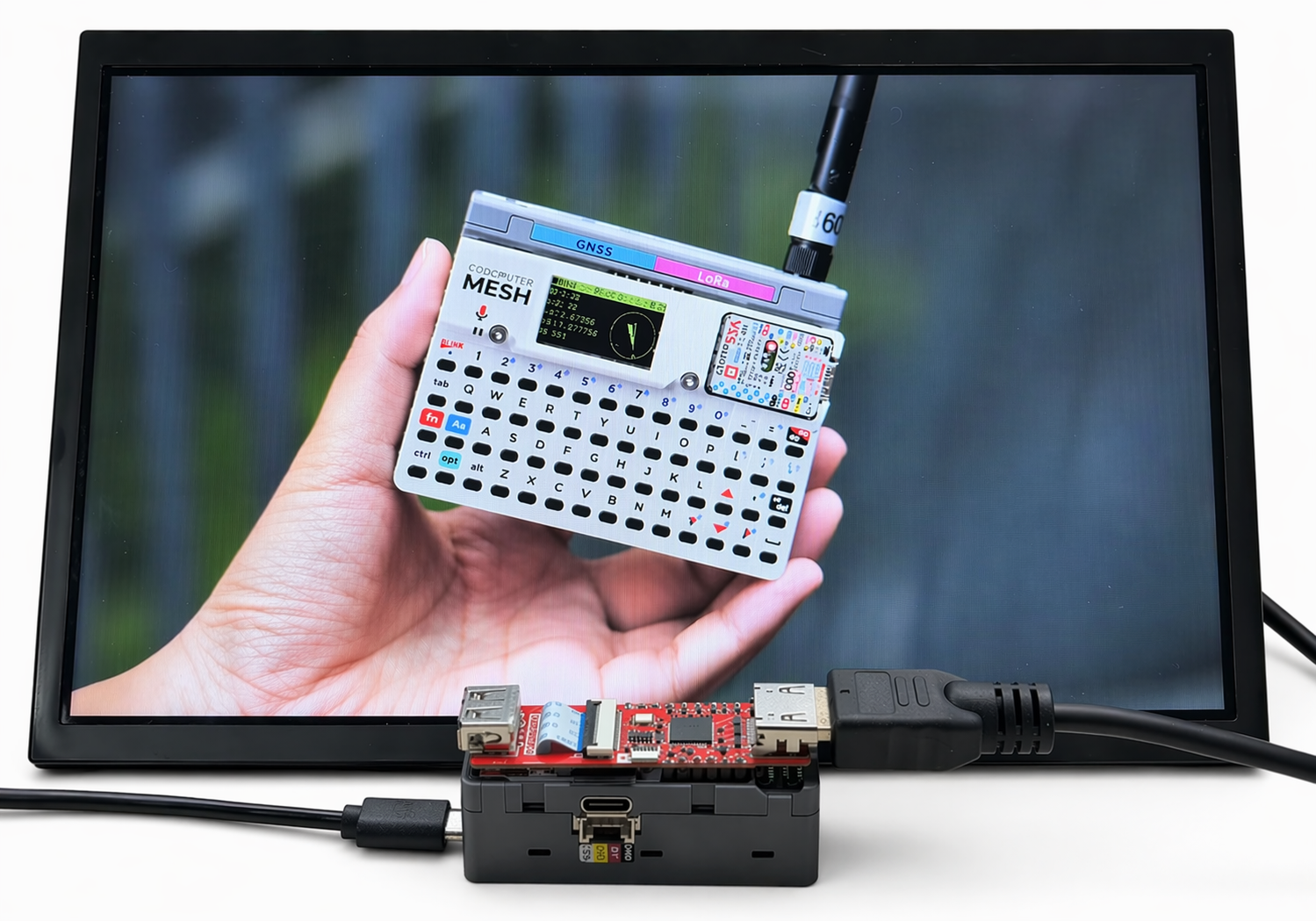
}成功运行后,Unit PoE-P4 会从 microSD 卡中读取图片文件,并在外接显示器上显示该图片。
显示联网图片
cpp
1 2 3 4 5 6 7 8 9 10 11 12 13 14 15 16 17 18 19 20 21 22 23 24 25 26 27 28 29 30 31 32 33 34 35 36 37 38 39 40 41 42 43 44 45 46 47 48 49 50 51 52 53 54 55 56 57 58 59 60 61 62 63 64 65 66 67 68 69 70 71 72 73 74 75 76 77 78 79 80 81 82 83 84 85 86 87 88 89 90 91 92 93 94 95 96 97 98 99 100 101 102 103 104 105 106 107 108 109 110 111 112 113 114 115 116 117 118 119 120 121 122 123 124 125 126 127 128 129 130 131 132 133 134 135 136 137 138 139 140 141 142 143 144 145 146 147 148 149 150 151 152 153 154 155 156 157 158 159 160 161 162 163 164 165 166 167 168 169 170 171 172 173 174 175 176 177 178 179 180
#include <ETH.h>
#include <HTTPClient.h>
#include <M5GFX.h>
#include <M5UnitPoEP4HDMI.h>

#define ETH_PHY_TYPE  ETH_PHY_IP101
#define ETH_PHY_ADDR  1
#define ETH_PHY_MDC   31
#define ETH_PHY_MDIO  52
#define ETH_PHY_POWER 51
#define ETH_CLK_MODE  EMAC_CLK_EXT_IN

namespace
{
M5UnitPoEP4HDMI::config_t makeDisplayConfig()
{
  M5UnitPoEP4HDMI::config_t cfg;
  // Unit PoE-P4 HDMI only supports 1280x720@60 or 1920x1080@30.
  // Set one of the supported timings explicitly here.
  cfg.width = 1280;
  cfg.height = 720;
  cfg.refresh_rate = 60;

  // Switch to 1080p30 by uncommenting the three lines below.
  // cfg.width = 1920;
  // cfg.height = 1080;
  // cfg.refresh_rate = 30;
  return cfg;
}
}

// Start the display with the selected HDMI timing.
M5UnitPoEP4HDMI display(makeDisplayConfig());

static const char *IMAGE_URL = "https://m5stack-doc.oss-cn-shenzhen.aliyuncs.com/1253/U221_AddOn_Display_Out_For_PoE-P4_Arduino_test_picture.jpg";
static bool eth_connected = false;

void onEvent(arduino_event_id_t event)
{
  switch (event)
  {
  case ARDUINO_EVENT_ETH_START:
    Serial.println("[ETH] Started");
    ETH.setHostname("unit-poe-p4");
    break;

  case ARDUINO_EVENT_ETH_CONNECTED:
    Serial.println("[ETH] Connected");
    break;

  case ARDUINO_EVENT_ETH_GOT_IP:
    Serial.println("[ETH] Got IP");
    Serial.println(ETH);
    eth_connected = true;
    break;

  case ARDUINO_EVENT_ETH_LOST_IP:
    Serial.println("[ETH] Lost IP");
    eth_connected = false;
    break;

  case ARDUINO_EVENT_ETH_DISCONNECTED:
    Serial.println("[ETH] Disconnected");
    eth_connected = false;
    break;

  case ARDUINO_EVENT_ETH_STOP:
    Serial.println("[ETH] Stopped");
    eth_connected = false;
    break;

  default:
    break;
  }
}

bool waitEthernet(uint32_t timeout_ms)
{
  uint32_t start = millis();
  while (!eth_connected && (millis() - start < timeout_ms))
  {
    Serial.printf(
        "[ETH] phyAddr=%lu, linkUp=%d, speed=%d Mbps, fullDuplex=%d, IP=%s\n",
        ETH.phyAddr(),
        ETH.linkUp(),
        ETH.linkSpeed(),
        ETH.fullDuplex(),
        ETH.localIP().toString().c_str());
    delay(1000);
  }

  return eth_connected;
}

void setup()
{
  Serial.begin(115200);
  delay(1000);

  // ---- 1. Display initialization ----
  Serial.println("[DISP] Initializing HDMI display...");
  display.begin();

  if (display.width() < display.height())
  {
    display.setRotation(display.getRotation() ^ 1);
  }

  display.fillScreen(TFT_BLACK);
  display.setTextColor(TFT_WHITE, TFT_BLACK);
  display.setTextSize(2);
  display.setTextDatum(datum_t::middle_center);
  display.drawString("Starting Ethernet...", display.width() / 2, display.height() / 2);

  // ---- 2. Ethernet initialization ----
  Network.onEvent(onEvent);
  Serial.println("[ETH] Initializing Ethernet...");
  bool eth_ok = ETH.begin(
      ETH_PHY_TYPE,
      ETH_PHY_ADDR,
      ETH_PHY_MDC,
      ETH_PHY_MDIO,
      ETH_PHY_POWER,
      ETH_CLK_MODE);

  Serial.printf("[ETH] ETH.begin result: %s\n", eth_ok ? "OK" : "FAILED");
  Serial.printf("[ETH] PHY addr: %lu\n", ETH.phyAddr());

  if (!eth_ok)
  {
    Serial.println("[ETH] ETH.begin() failed!");
    display.fillScreen(TFT_BLACK);
    display.setTextColor(TFT_RED, TFT_BLACK);
    display.drawString("ETH.begin Failed!", display.width() / 2, display.height() / 2);
    return;
  }

  display.fillScreen(TFT_BLACK);
  display.drawString("Waiting for IP...", display.width() / 2, display.height() / 2);

  bool network_ready = waitEthernet(20000);

  // ---- 3. Download and display JPEG ----
  if (network_ready)
  {
    Serial.printf("[ETH] Network ready. IP: %s\n", ETH.localIP().toString().c_str());

    display.fillScreen(TFT_BLACK);
    display.setTextColor(TFT_WHITE, TFT_BLACK);
    display.drawString("Downloading...", display.width() / 2, display.height() / 2);

    Serial.printf("[HTTP] Downloading: %s\n", IMAGE_URL);
    unsigned long dl_start = millis();
    bool ok = display.drawJpgUrl(IMAGE_URL, 0, 0);
    unsigned long dl_elapsed = millis() - dl_start;

    if (ok)
    {
      Serial.printf("[HTTP] Image displayed OK in %lu ms\n", dl_elapsed);
    }
    else
    {
      Serial.printf("[HTTP] Failed to download/decode after %lu ms\n", dl_elapsed);
      display.fillScreen(TFT_BLACK);
      display.drawString("Download Failed!", display.width() / 2, display.height() / 2);
    }
  }
  else
  {
    Serial.println("[ETH] Network timeout!");
    display.fillScreen(TFT_BLACK);
    display.setTextColor(TFT_RED, TFT_BLACK);
    display.drawString("Ethernet Timeout!", display.width() / 2, display.height() / 2);
  }
}

void loop(void)
{
  delay(1000);
}成功运行后,Unit PoE-P4 会通过以太网连接至互联网,并从指定 URL 下载 JPG 图片文件,然后在外接显示器上显示该图片。实际效果与 SD 卡图片演示示例相同。
串口输出示例:
[ETH] Initializing Ethernet...
[ETH] Started
[ETH] Connected
[ETH] ETH.begin result: OK
[ETH] PHY addr: 1
[ETH] phyAddr=1, linkUp=1, speed=100 Mbps, fullDuplex=1, IP=0.0.0.0
[ETH] phyAddr=1, linkUp=1, speed=100 Mbps, fullDuplex=1, IP=0.0.0.0
[ETH] phyAddr=1, linkUp=1, speed=100 Mbps, fullDuplex=1, IP=0.0.0.0
[ETH] phyAddr=1, linkUp=1, speed=100 Mbps, fullDuplex=1, IP=0.0.0.0
[ETH] phyAddr=1, linkUp=1, speed=100 Mbps, fullDuplex=1, IP=0.0.0.0
[ETH] Got IP
*eth0: <UP,100M,FULL_DUPLEX,AUTO,ADDR:0x1> (DHCPC,GARP,IP_MOD) PRIO: 50
      ether 80:F1:B2:D1:77:CC
      inet 192.168.20.91 netmask 255.255.255.0 broadcast 192.168.20.255
      gateway 192.168.20.1 dns 223.5.5.5
[ETH] Network ready. IP: 192.168.20.91
[HTTP] Downloading: https://m5stack-doc.oss-cn-shenzhen.aliyuncs.com/1253/U221_AddOn_Display_Out_For_PoE-P4_Arduino_test_picture.jpg
[HTTP] Image displayed OK in 1156 msPage Tools