Arduino 上手教程
2. 设备开发 & 案例程序
3. M5Unified
4. M5GFX
5. 扩展模块
Unit
Module
Atomic
Tab5
IoT
Unit 8Servos2-Chain Arduino 使用教程
1. 准备工作
环境配置:参考 Arduino IDE 上手教程 完成 IDE 安装,并根据实际使用的开发板安装对应的板管理与驱动库。
使用到的驱动库:
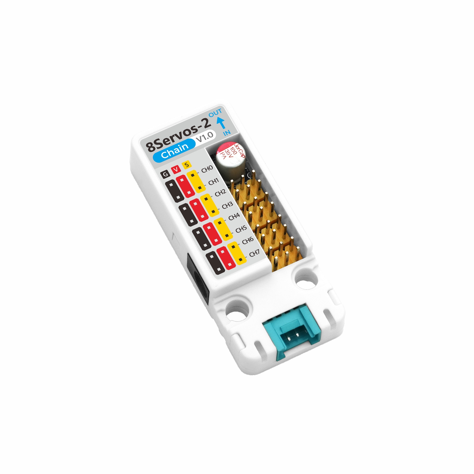
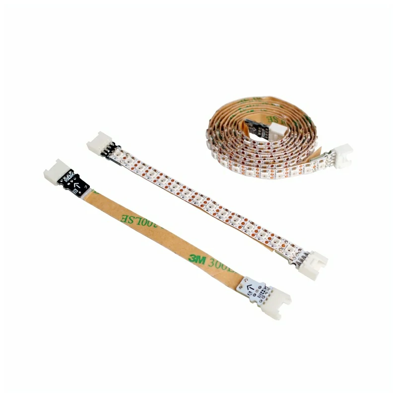
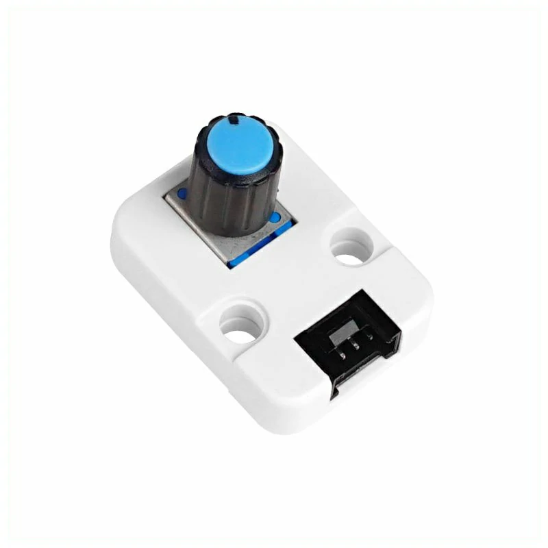
使用到的硬件产品:

2. 注意事项
3. 案例程序
- 本教程中使用的主控设备为 CoreS3,搭配 Unit 8Servos2-Chain 控制舵机。Unit 8Servos2-Chain 通过串口与主控通信,设备连接后对应的引脚为
G17 (TXD)、G18 (RXD)。
setup() 中将 cfg.output_power 设置为 true。3.1 舵机控制
#include <M5Unified.h>
#include "M5Chain.h"

#define TXD_PIN             17
#define RXD_PIN             18
#define SERVO_CHANNEL_COUNT 8
#define ANGLE_STEP          20
#define LOOP_DELAY_MS       200

// Chain state and device list.
Chain M5Chain;
device_list_t *devices_list = nullptr;
uint16_t device_nums = 0;
uint8_t operation_status = 0;
uint8_t angle = 0;
bool servo_ready = false;
M5Canvas canvas(&M5.Display);

void showMessage(const char *message)
{
    // Show a status message on the display.
    canvas.clear();
    canvas.setCursor(0, 0);
    canvas.println(message);
    canvas.pushSprite(0, 0);
}

bool updateDeviceList()
{
    // Discover all devices on the Chain bus.
    if (!M5Chain.isDeviceConnected()) {
        Serial.println("Chain device not connected");
        return false;
    }

    if (M5Chain.getDeviceNum(&device_nums) != CHAIN_OK || device_nums == 0) {
        Serial.println("Failed to get Chain device count");
        return false;
    }

    // Allocate storage for the device list returned by M5Chain.
    devices_list = (device_list_t *)malloc(sizeof(device_list_t));
    if (devices_list == nullptr) {
        Serial.println("Failed to allocate device list");
        return false;
    }

    devices_list->count = device_nums;
    devices_list->devices = (device_info_t *)malloc(sizeof(device_info_t) * device_nums);
    if (devices_list->devices == nullptr) {
        free(devices_list);
        devices_list = nullptr;
        Serial.println("Failed to allocate device information");
        return false;
    }

    if (!M5Chain.getDeviceList(devices_list)) {
        free(devices_list->devices);
        free(devices_list);
        devices_list = nullptr;
        Serial.println("Failed to get Chain device list");
        return false;
    }

    // Print the detected device IDs and types.
    Serial.printf("Chain device count: %u\r\n", devices_list->count);
    for (uint8_t i = 0; i < devices_list->count; i++) {
        Serial.printf("ID[%u], type: 0x%02X\r\n", devices_list->devices[i].id,
                      devices_list->devices[i].device_type);
    }
    return true;
}

bool initializeServoMode()
{
    if (devices_list == nullptr) {
        return false;
    }

    // Configure all eight channels as servo outputs.
    user_gpio_mode_t modes[SERVO_CHANNEL_COUNT];
    for (uint8_t i = 0; i < SERVO_CHANNEL_COUNT; i++) {
        modes[i] = USER_GPIO_SERVO_MODE;
    }

    bool found = false;
    for (uint8_t i = 0; i < devices_list->count; i++) {
        if (devices_list->devices[i].device_type != UNIT_8SERVOS2_CHAIN_TYPE_CODE) {
            continue;
        }

        found = true;
        uint8_t device_id = devices_list->devices[i].id;
        chain_status_t status = M5Chain.setServosModeAll(
            device_id, modes, SERVO_CHANNEL_COUNT, &operation_status);
        if (status != CHAIN_OK || operation_status != 1) {
            Serial.printf("ID[%u] servo mode setup failed\r\n", device_id);
            continue;
        }

        Serial.printf("ID[%u] servo mode setup success\r\n", device_id);
    }
    return found;
}

bool setAndVerifyAngle(uint8_t target_angle)
{
    if (devices_list == nullptr) {
        return false;
    }

    // Set the same target angle on every servo channel.
    uint8_t target_angles[SERVO_CHANNEL_COUNT];
    uint8_t read_angles[SERVO_CHANNEL_COUNT] = {0};
    for (uint8_t i = 0; i < SERVO_CHANNEL_COUNT; i++) {
        target_angles[i] = target_angle;
    }

    bool all_success = true;
    for (uint8_t i = 0; i < devices_list->count; i++) {
        if (devices_list->devices[i].device_type != UNIT_8SERVOS2_CHAIN_TYPE_CODE) {
            continue;
        }

        uint8_t device_id = devices_list->devices[i].id;
        chain_status_t status = M5Chain.setServosAngleAll(
            device_id, target_angles, SERVO_CHANNEL_COUNT, &operation_status);
        if (status != CHAIN_OK || operation_status != 1 ||
            M5Chain.getServosAngleAll(device_id, read_angles, SERVO_CHANNEL_COUNT) != CHAIN_OK) {
            Serial.printf("ID[%u] angle operation failed\r\n", device_id);
            all_success = false;
            continue;
        }

        // Verify every channel by reading the angle back.
        for (uint8_t channel = 0; channel < SERVO_CHANNEL_COUNT; channel++) {
            if (read_angles[channel] != target_angle) {
                Serial.printf("ID[%u] CH[%u] angle mismatch: %u / %u\r\n",
                              device_id, channel, target_angle, read_angles[channel]);
                all_success = false;
            }
        }
    }
    return all_success;
}

bool readAndDisplayPower(uint8_t current_angle)
{
    if (devices_list == nullptr) {
        return false;
    }

    // Read voltage and current telemetry from each matching device.
    bool all_success = true;
    bool display_updated = false;
    for (uint8_t i = 0; i < devices_list->count; i++) {
        if (devices_list->devices[i].device_type != UNIT_8SERVOS2_CHAIN_TYPE_CODE) {
            continue;
        }

        uint8_t device_id = devices_list->devices[i].id;
        uint16_t dc_voltage = 0;
        uint16_t grove_voltage = 0;
        uint16_t system_current = 0;
        chain_status_t dc_status = M5Chain.getServosDcVoltage(device_id, &dc_voltage);
        chain_status_t grove_status = M5Chain.getServosGroveVoltage(device_id, &grove_voltage);
        chain_status_t current_status = M5Chain.getServosSysCurrent(device_id, &system_current);

        if (dc_status != CHAIN_OK || grove_status != CHAIN_OK || current_status != CHAIN_OK) {
            Serial.printf("ID[%u] power monitor failed: DC=%d, Grove=%d, Current=%d\r\n",
                          device_id, dc_status, grove_status, current_status);
            all_success = false;
            continue;
        }

        Serial.printf("ID[%u] power: DC=%umV, Grove=%umV, Current=%umA\r\n",
                      device_id, dc_voltage, grove_voltage, system_current);

        // Display the first matching device while logging all devices.
        if (!display_updated) {
            canvas.clear();
            canvas.setCursor(0, 0);
            canvas.println("Unit 8Servos2-Chain");
            canvas.setCursor(0, 40);
            canvas.printf("Angle: %u", current_angle);
            canvas.setCursor(0, 80);
            canvas.printf("DC: %umV", dc_voltage);
            canvas.setCursor(0, 120);
            canvas.printf("Current: %umA", system_current);
            canvas.setCursor(0, 160);
            canvas.printf("Grove: %umV", grove_voltage);
            canvas.pushSprite(0, 0);
            display_updated = true;
        }
    }
    return all_success;
}

void setup()
{
    // Disable 5V output on the CoreS3 Grove port.
    auto cfg = M5.config();
    cfg.output_power = false;
    M5.begin(cfg);
    canvas.createSprite(320, 240);
    canvas.setFont(&fonts::FreeMonoBold12pt7b);
    canvas.setTextSize(1);
    Serial.begin(115200);
    Serial.println("Unit 8Servos2-Chain Test");

    // Start Chain UART communication.
    M5Chain.begin(&Serial2, 115200, RXD_PIN, TXD_PIN);
    if (!updateDeviceList()) {
        showMessage("Chain device not found");
        return;
    }

    servo_ready = initializeServoMode();
    if (!servo_ready) {
        showMessage("8Servos2-Chain not found");
        return;
    }
    showMessage("8Servos2-Chain ready");
}

void loop()
{
    if (!servo_ready) {
        delay(LOOP_DELAY_MS);
        return;
    }

    // Set the next angle and verify the response.
    if (setAndVerifyAngle(angle)) {
        Serial.printf("All servo channels set to %u degrees\r\n", angle);
    } else {
        Serial.println("Servo angle operation failed");
    }

    // Update the power monitor display and serial log.
    readAndDisplayPower(angle);

    // Advance through the 0-180 degree test range.
    angle += ANGLE_STEP;
    if (angle > 180) {
        angle = 0;
    }
    delay(LOOP_DELAY_MS);
}设备上电后,程序会在串口监视器输出 Chain 总线设备数量、设备 ID 和设备类型,并查找 Unit 8Servos2-Chain。找到设备后,程序将所有通道配置为舵机模式,然后以 20° 为步进在 0° ~ 180° 范围内循环设置舵机角度,并读取 DC 输入电压、Grove 接口电压和系统总电流。实际连接多台 Unit 8Servos2-Chain 时,串口会分别输出每台设备的监测数据,屏幕显示第一台检测到的设备数据。
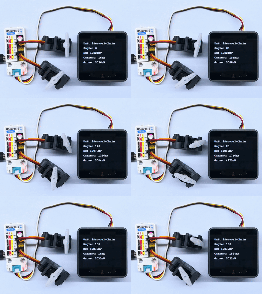
串口返回信息示例如下:
Unit 8Servos2-Chain Test
Chain device count: 1
ID[1], type: 0x0C
ID[1] servo mode setup success
All servo channels set to 0 degrees
ID[1] power: DC=12254mV, Grove=5046mV, Current=1768mA
All servo channels set to 20 degrees
ID[1] power: DC=12254mV, Grove=5046mV, Current=12mA
All servo channels set to 40 degrees
ID[1] power: DC=12265mV, Grove=5046mV, Current=1700mA
All servo channels set to 60 degrees
ID[1] power: DC=12265mV, Grove=5044mV, Current=12mA
All servo channels set to 80 degrees
ID[1] power: DC=12265mV, Grove=5046mV, Current=1590mA
All servo channels set to 100 degrees
ID[1] power: DC=12254mV, Grove=5044mV, Current=20mA
All servo channels set to 120 degrees
ID[1] power: DC=12243mV, Grove=5008mV, Current=1522mA
All servo channels set to 140 degrees
ID[1] power: DC=12254mV, Grove=5046mV, Current=10mA
All servo channels set to 160 degrees
ID[1] power: DC=12254mV, Grove=5004mV, Current=1488mA
All servo channels set to 180 degrees
ID[1] power: DC=12265mV, Grove=5044mV, Current=12mA3.2 输入、输出控制
#include <M5Unified.h>
#include "M5Chain.h"

#define TXD_PIN       17
#define RXD_PIN       18
#define GPIO_COUNT    8
#define CH0           0
#define CH3           3
#define CH4           4
#define CH7           7
#define LOOP_DELAY_MS 500

// Chain state and device list.
Chain M5Chain;
device_list_t *devices_list = nullptr;
uint16_t device_nums = 0;
uint8_t operation_status = 0;
uint8_t unit_id = 0;
bool unit_ready = false;
bool output_level = false;
M5Canvas canvas(&M5.Display);

void showMessage(const char *message)
{
    // Show a status message on the display.
    canvas.clear();
    canvas.setCursor(0, 0);
    canvas.println(message);
    canvas.pushSprite(0, 0);
}

bool updateDeviceList()
{
    // Discover the Unit 8Servos2-Chain device.
    if (!M5Chain.isDeviceConnected()) {
        Serial.println("Chain device not connected");
        return false;
    }

    if (M5Chain.getDeviceNum(&device_nums) != CHAIN_OK || device_nums == 0) {
        Serial.println("Failed to get Chain device count");
        return false;
    }

    devices_list = (device_list_t *)malloc(sizeof(device_list_t));
    if (devices_list == nullptr) {
        Serial.println("Failed to allocate device list");
        return false;
    }

    devices_list->count = device_nums;
    devices_list->devices = (device_info_t *)malloc(sizeof(device_info_t) * device_nums);
    if (devices_list->devices == nullptr || !M5Chain.getDeviceList(devices_list)) {
        free(devices_list->devices);
        free(devices_list);
        devices_list = nullptr;
        Serial.println("Failed to get Chain device list");
        return false;
    }

    for (uint8_t i = 0; i < devices_list->count; i++) {
        if (devices_list->devices[i].device_type == UNIT_8SERVOS2_CHAIN_TYPE_CODE) {
            unit_id = devices_list->devices[i].id;
            break;
        }
    }
    return unit_id != 0;
}

bool configureChannels()
{
    // Configure CH0 and CH4 as outputs, and CH3 and CH7 as inputs.
    user_gpio_mode_t modes[GPIO_COUNT];
    for (uint8_t i = 0; i < GPIO_COUNT; i++) {
        modes[i] = USER_GPIO_INPUT_MODE;
    }
    modes[CH0] = USER_GPIO_OUTPUT_MODE;
    modes[CH4] = USER_GPIO_OUTPUT_MODE;

    chain_status_t status = M5Chain.setServosModeAll(
        unit_id, modes, GPIO_COUNT, &operation_status);
    if (status != CHAIN_OK || operation_status != 1) {
        return false;
    }

    if (M5Chain.setServosInputPuPd(unit_id, CH3, USER_GPIO_PULL_DOWN, &operation_status) != CHAIN_OK ||
        operation_status != 1) {
        return false;
    }
    if (M5Chain.setServosInputPuPd(unit_id, CH7, USER_GPIO_PULL_DOWN, &operation_status) != CHAIN_OK ||
        operation_status != 1) {
        return false;
    }

    return true;
}

const char *levelName(user_sys_gpio_level_t level)
{
    return level == USER_GPIO_LEVEL_HIGH ? "HIGH" : "LOW";
}

void updateOutputAndDisplay()
{
    // Set CH0 and CH4 to opposite levels at the same update step.
    user_sys_gpio_level_t ch0_level = output_level ? USER_GPIO_LEVEL_HIGH : USER_GPIO_LEVEL_LOW;
    user_sys_gpio_level_t ch4_level = output_level ? USER_GPIO_LEVEL_LOW : USER_GPIO_LEVEL_HIGH;
    bool output_success =
        M5Chain.setServosOutputLevel(unit_id, CH0, ch0_level, &operation_status) == CHAIN_OK &&
        operation_status == 1;
    output_success =
        M5Chain.setServosOutputLevel(unit_id, CH4, ch4_level, &operation_status) == CHAIN_OK &&
        operation_status == 1 && output_success;

    user_sys_gpio_level_t ch3_level = USER_GPIO_LEVEL_LOW;
    user_sys_gpio_level_t ch7_level = USER_GPIO_LEVEL_LOW;
    bool input_success =
        M5Chain.getServosInputLevel(unit_id, CH3, &ch3_level, &operation_status) == CHAIN_OK &&
        operation_status == 1;
    input_success =
        M5Chain.getServosInputLevel(unit_id, CH7, &ch7_level, &operation_status) == CHAIN_OK &&
        operation_status == 1 && input_success;

    canvas.clear();
    canvas.setCursor(0, 0);
    canvas.println("Unit 8Servos2-Chain");
    canvas.setCursor(0, 40);
    canvas.printf("CH0 OUT: %s", levelName(ch0_level));
    canvas.setCursor(0, 80);
    canvas.printf("CH4 OUT: %s", levelName(ch4_level));
    canvas.setCursor(0, 120);
    canvas.printf("CH3 IN:  %s", input_success ? levelName(ch3_level) : "ERROR");
    canvas.setCursor(0, 160);
    canvas.printf("CH7 IN:  %s", input_success ? levelName(ch7_level) : "ERROR");
    canvas.pushSprite(0, 0);

    Serial.printf("CH0=%s, CH4=%s, CH3=%s, CH7=%s\r\n",
                  output_success ? levelName(ch0_level) : "ERROR",
                  output_success ? levelName(ch4_level) : "ERROR",
                  input_success ? levelName(ch3_level) : "ERROR",
                  input_success ? levelName(ch7_level) : "ERROR");
    output_level = !output_level;
}

void setup()
{
    // Disable 5V output on the CoreS3 Grove port.
    auto cfg = M5.config();
    cfg.output_power = false;
    M5.begin(cfg);
    canvas.createSprite(320, 240);
    canvas.setFont(&fonts::FreeMonoBold12pt7b);
    canvas.setTextSize(1);
    Serial.begin(115200);
    Serial.println("Unit 8Servos2-Chain GPIO Test");

    // Start Chain UART communication.
    M5Chain.begin(&Serial2, 115200, RXD_PIN, TXD_PIN);
    if (!updateDeviceList() || !configureChannels()) {
        showMessage("GPIO setup failed");
        return;
    }
    unit_ready = true;
    showMessage("GPIO test ready");
}

void loop()
{
    if (!unit_ready) {
        delay(LOOP_DELAY_MS);
        return;
    }

    updateOutputAndDisplay();
    delay(LOOP_DELAY_MS);
}
设备上电后,程序会在串口监视器输出 Chain 总线设备数量、设备 ID 和设备类型,并查找 Unit 8Servos2-Chain。找到设备后,程序将 CH0 和 CH4 配置为输出模式,CH3 和 CH7 配置为输入模式,并启用下拉电阻。程序会以 500ms 为周期循环设置 CH0 和 CH4 输出相反的电平,同时读取 CH3 和 CH7 的输入电平。屏幕显示当前输出和输入状态,串口输出相同数据。
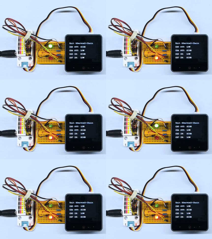
3.3 ADC 采集
#include <M5Unified.h>
#include "M5Chain.h"

#define TXD_PIN       17
#define RXD_PIN       18
#define GPIO_COUNT    8
#define ADC_CHANNEL   4
#define LOOP_DELAY_MS 100

// Chain state and device list.
Chain M5Chain;
device_list_t *devices_list = nullptr;
uint16_t device_nums = 0;
uint8_t operation_status = 0;
uint8_t unit_id = 0;
bool unit_ready = false;
M5Canvas canvas(&M5.Display);

void showMessage(const char *message)
{
    // Show a status message on the display.
    canvas.clear();
    canvas.setCursor(0, 0);
    canvas.println(message);
    canvas.pushSprite(0, 0);
}

bool updateDeviceList()
{
    // Discover the Unit 8Servos2-Chain device.
    if (!M5Chain.isDeviceConnected()) {
        Serial.println("Chain device not connected");
        return false;
    }

    if (M5Chain.getDeviceNum(&device_nums) != CHAIN_OK || device_nums == 0) {
        Serial.println("Failed to get Chain device count");
        return false;
    }

    devices_list = (device_list_t *)malloc(sizeof(device_list_t));
    if (devices_list == nullptr) {
        Serial.println("Failed to allocate device list");
        return false;
    }

    devices_list->count = device_nums;
    devices_list->devices = (device_info_t *)malloc(sizeof(device_info_t) * device_nums);
    if (devices_list->devices == nullptr || !M5Chain.getDeviceList(devices_list)) {
        free(devices_list->devices);
        free(devices_list);
        devices_list = nullptr;
        Serial.println("Failed to get Chain device list");
        return false;
    }

    for (uint8_t i = 0; i < devices_list->count; i++) {
        if (devices_list->devices[i].device_type == UNIT_8SERVOS2_CHAIN_TYPE_CODE) {
            unit_id = devices_list->devices[i].id;
            break;
        }
    }
    return unit_id != 0;
}

bool configureAdc()
{
    // Configure CH4 for ADC and keep the other channels as digital inputs.
    user_gpio_mode_t modes[GPIO_COUNT];
    for (uint8_t i = 0; i < GPIO_COUNT; i++) {
        modes[i] = USER_GPIO_INPUT_MODE;
    }
    modes[ADC_CHANNEL] = USER_GPIO_ADC_MODE;

    chain_status_t status = M5Chain.setServosModeAll(
        unit_id, modes, GPIO_COUNT, &operation_status);
    return status == CHAIN_OK && operation_status == 1;
}

void readAndDisplayAdc()
{
    // Read the CH4 ADC value continuously.
    uint16_t adc_value = 0;
    bool success = M5Chain.getServosAdcValue(
                       unit_id, ADC_CHANNEL, &adc_value, &operation_status) == CHAIN_OK &&
                   operation_status == 1;

    canvas.clear();
    canvas.setCursor(0, 0);
    canvas.println("Unit 8Servos2-Chain");
    canvas.setCursor(0, 40);
    canvas.println("ADC monitor");
    canvas.setCursor(0, 80);
    canvas.printf("CH4: %s", success ? "READY" : "ERROR");
    canvas.setCursor(0, 120);
    canvas.printf("Value: %u", adc_value);
    canvas.pushSprite(0, 0);

    Serial.printf("CH4 ADC: %s, value=%u\r\n", success ? "OK" : "ERROR", adc_value);
}

void setup()
{
    // Disable 5V output on the CoreS3 Grove port.
    auto cfg = M5.config();
    cfg.output_power = false;
    M5.begin(cfg);
    canvas.createSprite(320, 240);
    canvas.setFont(&fonts::FreeMonoBold12pt7b);
    canvas.setTextSize(1);
    Serial.begin(115200);
    Serial.println("Unit 8Servos2-Chain ADC Test");

    // Start Chain UART communication.
    M5Chain.begin(&Serial2, 115200, RXD_PIN, TXD_PIN);
    if (!updateDeviceList() || !configureAdc()) {
        showMessage("ADC setup failed");
        return;
    }
    unit_ready = true;
    showMessage("ADC test ready");
}

void loop()
{
    if (!unit_ready) {
        delay(LOOP_DELAY_MS);
        return;
    }

    readAndDisplayAdc();
    delay(LOOP_DELAY_MS);
}
程序启动后,将 CH4 设置为 ADC 模式,持续读取 CH4 的 ADC 原始值。CoreS3 屏幕显示当前通道和 ADC 值,串口同步输出采集状态和结果,程序每 100ms 更新一次。
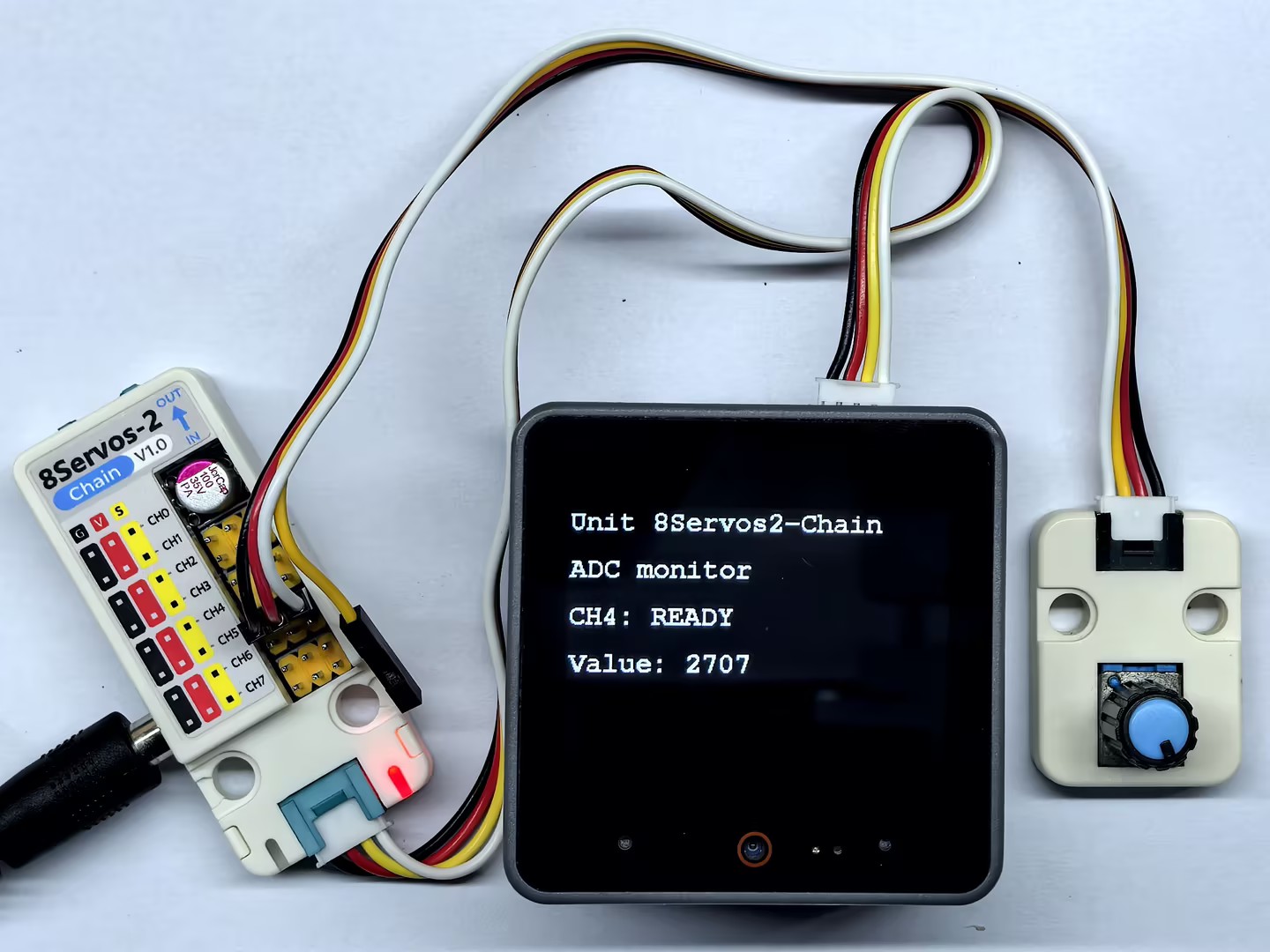
3.4 PWM 输出
#include <M5Unified.h>
#include "M5Chain.h"

#define TXD_PIN       17
#define RXD_PIN       18
#define GPIO_COUNT    8
#define CH0           0
#define CH4           4
#define PWM_MAX_DUTY  100
#define DUTY_STEP     10
#define LOOP_DELAY_MS 50

// Chain state and device list.
Chain M5Chain;
device_list_t *devices_list = nullptr;
uint16_t device_nums = 0;
uint8_t operation_status = 0;
uint8_t unit_id = 0;
bool unit_ready = false;
uint8_t ch0_duty = 0;
uint8_t ch4_duty = PWM_MAX_DUTY;
bool duty_increasing = true;
M5Canvas canvas(&M5.Display);

void showMessage(const char *message)
{
    // Show a status message on the display.
    canvas.clear();
    canvas.setCursor(0, 0);
    canvas.println(message);
    canvas.pushSprite(0, 0);
}

bool updateDeviceList()
{
    // Discover the Unit 8Servos2-Chain device.
    if (!M5Chain.isDeviceConnected()) {
        Serial.println("Chain device not connected");
        return false;
    }

    if (M5Chain.getDeviceNum(&device_nums) != CHAIN_OK || device_nums == 0) {
        Serial.println("Failed to get Chain device count");
        return false;
    }

    devices_list = (device_list_t *)malloc(sizeof(device_list_t));
    if (devices_list == nullptr) {
        Serial.println("Failed to allocate device list");
        return false;
    }

    devices_list->count = device_nums;
    devices_list->devices = (device_info_t *)malloc(sizeof(device_info_t) * device_nums);
    if (devices_list->devices == nullptr || !M5Chain.getDeviceList(devices_list)) {
        free(devices_list->devices);
        free(devices_list);
        devices_list = nullptr;
        Serial.println("Failed to get Chain device list");
        return false;
    }

    for (uint8_t i = 0; i < devices_list->count; i++) {
        if (devices_list->devices[i].device_type == UNIT_8SERVOS2_CHAIN_TYPE_CODE) {
            unit_id = devices_list->devices[i].id;
            break;
        }
    }
    return unit_id != 0;
}

bool configurePwm()
{
    // Configure CH0 and CH4 for PWM output.
    user_gpio_mode_t modes[GPIO_COUNT];
    for (uint8_t i = 0; i < GPIO_COUNT; i++) {
        modes[i] = USER_GPIO_INPUT_MODE;
    }
    modes[CH0] = USER_GPIO_PWM_MODE;
    modes[CH4] = USER_GPIO_PWM_MODE;

    chain_status_t status = M5Chain.setServosModeAll(
        unit_id, modes, GPIO_COUNT, &operation_status);
    return status == CHAIN_OK && operation_status == 1;
}

void updatePwmAndDisplay()
{
    // Change one duty cycle up and the other down every 200 ms.
    if (duty_increasing) {
        if (ch0_duty <= PWM_MAX_DUTY - DUTY_STEP) {
            ch0_duty += DUTY_STEP;
        } else {
            ch0_duty = PWM_MAX_DUTY;
        }
        if (ch4_duty >= DUTY_STEP) {
            ch4_duty -= DUTY_STEP;
        } else {
            ch4_duty = 0;
        }
        if (ch0_duty == PWM_MAX_DUTY || ch4_duty == 0) {
            duty_increasing = false;
        }
    } else {
        if (ch0_duty >= DUTY_STEP) {
            ch0_duty -= DUTY_STEP;
        } else {
            ch0_duty = 0;
        }
        if (ch4_duty <= PWM_MAX_DUTY - DUTY_STEP) {
            ch4_duty += DUTY_STEP;
        } else {
            ch4_duty = PWM_MAX_DUTY;
        }
        if (ch0_duty == 0 || ch4_duty == PWM_MAX_DUTY) {
            duty_increasing = true;
        }
    }

    bool ch0_success =
        M5Chain.setServosPwmDuty(unit_id, CH0, ch0_duty, &operation_status) == CHAIN_OK &&
        operation_status == 1;
    bool ch4_success =
        M5Chain.setServosPwmDuty(unit_id, CH4, ch4_duty, &operation_status) == CHAIN_OK &&
        operation_status == 1;

    canvas.clear();
    canvas.setCursor(0, 0);
    canvas.println("Unit 8Servos2-Chain");
    canvas.setCursor(0, 40);
    canvas.println("PWM output");
    canvas.setCursor(0, 80);
    canvas.printf("CH0: %3u%% %s", ch0_duty, ch0_success ? "OK" : "ERR");
    canvas.setCursor(0, 120);
    canvas.printf("CH4: %3u%% %s", ch4_duty, ch4_success ? "OK" : "ERR");
    canvas.setCursor(0, 160);
    canvas.printf("Direction: %s", duty_increasing ? "UP" : "DOWN");
    canvas.pushSprite(0, 0);

    Serial.printf("PWM CH0=%u (%s), CH4=%u (%s), direction=%s\r\n",
                  ch0_duty, ch0_success ? "OK" : "ERROR",
                  ch4_duty, ch4_success ? "OK" : "ERROR",
                  duty_increasing ? "UP" : "DOWN");
}

void setup()
{
    // Disable 5V output on the CoreS3 Grove port.
    auto cfg = M5.config();
    cfg.output_power = false;
    M5.begin(cfg);
    canvas.createSprite(320, 240);
    canvas.setFont(&fonts::FreeMonoBold12pt7b);
    canvas.setTextSize(1);
    Serial.begin(115200);
    Serial.println("Unit 8Servos2-Chain PWM Test");

    // Start Chain UART communication.
    M5Chain.begin(&Serial2, 115200, RXD_PIN, TXD_PIN);
    if (!updateDeviceList() || !configurePwm()) {
        showMessage("PWM setup failed");
        return;
    }
    unit_ready = true;
    showMessage("PWM test ready");
}

void loop()
{
    if (!unit_ready) {
        delay(LOOP_DELAY_MS);
        return;
    }

    updatePwmAndDisplay();
    delay(LOOP_DELAY_MS);
}
程序启动后,将 CH0 和 CH4 设置为 PWM 输出模式。程序每 50ms 调整一次占空比,CH0 增加时 CH4 同步减少,达到 0% 或 100% 后切换调整方向。CoreS3 屏幕和串口显示两个通道的当前占空比及变化方向。
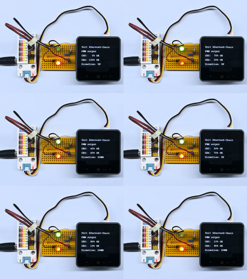
3.5 RGB 灯控制
#include <M5Unified.h>
#include "M5Chain.h"

#define TXD_PIN        17
#define RXD_PIN        18
#define GPIO_COUNT     8
#define RGB_CHANNEL    2
#define RGB_LED_COUNT  15
#define RGB_BUFFER_COUNT 16
#define RAINBOW_DURATION_MS 1000
#define RAINBOW_DELAY_MS    20

// Chain state and device list.
Chain M5Chain;
device_list_t *devices_list = nullptr;
uint16_t device_nums = 0;
uint8_t operation_status = 0;
uint8_t unit_id = 0;
bool unit_ready = false;
M5Canvas canvas(&M5.Display);

void showMessage(const char *message)
{
    // Show a status message on the display.
    canvas.clear();
    canvas.setCursor(0, 0);
    canvas.println(message);
    canvas.pushSprite(0, 0);
}

bool updateDeviceList()
{
    // Discover the Unit 8Servos2-Chain device.
    if (!M5Chain.isDeviceConnected()) {
        Serial.println("Chain device not connected");
        return false;
    }

    if (M5Chain.getDeviceNum(&device_nums) != CHAIN_OK || device_nums == 0) {
        Serial.println("Failed to get Chain device count");
        return false;
    }

    devices_list = (device_list_t *)malloc(sizeof(device_list_t));
    if (devices_list == nullptr) {
        Serial.println("Failed to allocate device list");
        return false;
    }

    devices_list->count = device_nums;
    devices_list->devices = (device_info_t *)malloc(sizeof(device_info_t) * device_nums);
    if (devices_list->devices == nullptr || !M5Chain.getDeviceList(devices_list)) {
        free(devices_list->devices);
        free(devices_list);
        devices_list = nullptr;
        Serial.println("Failed to get Chain device list");
        return false;
    }

    for (uint8_t i = 0; i < devices_list->count; i++) {
        if (devices_list->devices[i].device_type == UNIT_8SERVOS2_CHAIN_TYPE_CODE) {
            unit_id = devices_list->devices[i].id;
            break;
        }
    }
    return unit_id != 0;
}

bool configureRgb()
{
    // Configure CH2 as an RGB strip control channel.
    user_gpio_mode_t modes[GPIO_COUNT];
    for (uint8_t i = 0; i < GPIO_COUNT; i++) {
        modes[i] = USER_GPIO_INPUT_MODE;
    }
    modes[RGB_CHANNEL] = USER_GPIO_RGB_MODE;

    chain_status_t status = M5Chain.setServosModeAll(
        unit_id, modes, GPIO_COUNT, &operation_status);
    if (status != CHAIN_OK || operation_status != 1) {
        return false;
    }

    return true;
}

uint32_t wheel(uint8_t position)
{
    // Convert a position on the color wheel to 0xRRGGBB.
    position = 255 - position;
    if (position < 85) {
        return ((uint32_t)(255 - position * 3) << 16) |
               ((uint32_t)(position * 3) << 8);
    }
    if (position < 170) {
        position -= 85;
        return ((uint32_t)(position * 3) << 16) |
               (uint32_t)(255 - position * 3);
    }
    position -= 170;
    return ((uint32_t)(255 - position * 3) << 8) |
           (uint32_t)(position * 3);
}

bool setStripColor(uint32_t color, const char *name)
{
    // Set one color on every LED in the strip.
    // M5Chain requires a 16-entry RGB buffer; the last entry is unused.
    uint32_t colors[RGB_BUFFER_COUNT] = {0};
    for (uint8_t i = 0; i < RGB_LED_COUNT; i++) {
        colors[i] = color;
    }
    bool success = M5Chain.setServosRGBBufferAll(unit_id, colors, RGB_BUFFER_COUNT) == CHAIN_OK;
    uint8_t rgb_config = 0x20 | RGB_LED_COUNT;
    success = M5Chain.setServosRGBConfig(unit_id, RGB_CHANNEL, rgb_config, &operation_status) == CHAIN_OK &&
              operation_status == 1 && success;

    canvas.clear();
    canvas.setCursor(0, 0);
    canvas.println("Unit 8Servos2-Chain");
    canvas.setCursor(0, 40);
    canvas.println("RGB strip");
    canvas.setCursor(0, 80);
    canvas.printf("Color: %s", success ? name : "ERROR");
    canvas.setCursor(0, 120);
    canvas.printf("CH2 LEDs: %u", RGB_LED_COUNT);
    canvas.pushSprite(0, 0);
    Serial.printf("RGB %s: %s\r\n", name, success ? "OK" : "ERROR");
    return success;
}

bool setRainbowStep(uint8_t step)
{
    // Shift the rainbow pattern across the strip.
    // M5Chain requires a 16-entry RGB buffer; the last entry is unused.
    uint32_t colors[RGB_BUFFER_COUNT] = {0};
    for (uint8_t i = 0; i < RGB_LED_COUNT; i++) {
        uint8_t position = (uint8_t)((uint16_t)i * 256 / RGB_LED_COUNT - step * 26);
        colors[i] = wheel(position);
    }
    bool success = M5Chain.setServosRGBBufferAll(unit_id, colors, RGB_BUFFER_COUNT) == CHAIN_OK;
    uint8_t rgb_config = 0x20 | RGB_LED_COUNT;
    success = M5Chain.setServosRGBConfig(unit_id, RGB_CHANNEL, rgb_config, &operation_status) == CHAIN_OK &&
              operation_status == 1 && success;

    canvas.clear();
    canvas.setCursor(0, 0);
    canvas.println("Unit 8Servos2-Chain");
    canvas.setCursor(0, 40);
    canvas.println("RGB strip");
    canvas.setCursor(0, 80);
    canvas.printf("Color: %s", success ? "RAINBOW" : "ERROR");
    canvas.setCursor(0, 120);
    canvas.printf("Step: %u", step);
    canvas.pushSprite(0, 0);
    return success;
}

void setup()
{
    // Disable 5V output on the CoreS3 Grove port.
    auto cfg = M5.config();
    cfg.output_power = false;
    M5.begin(cfg);
    canvas.createSprite(320, 240);
    canvas.setFont(&fonts::FreeMonoBold12pt7b);
    canvas.setTextSize(1);
    Serial.begin(115200);
    Serial.println("Unit 8Servos2-Chain RGB Test");

    // Start Chain UART communication.
    M5Chain.begin(&Serial2, 115200, RXD_PIN, TXD_PIN);
    if (!updateDeviceList() || !configureRgb()) {
        showMessage("RGB setup failed");
        return;
    }
    unit_ready = true;
    showMessage("RGB test ready");
}

void loop()
{
    if (!unit_ready) {
        delay(RAINBOW_DELAY_MS);
        return;
    }

    setStripColor(0xFF0000, "RED");
    delay(500);
    setStripColor(0x00FF00, "GREEN");
    delay(500);
    setStripColor(0x0000FF, "BLUE");
    delay(500);

    // Run a fast rainbow animation continuously for one second.
    uint32_t rainbow_start = millis();
    uint8_t step = 0;
    while (millis() - rainbow_start < RAINBOW_DURATION_MS) {
        setRainbowStep(step++);
        delay(RAINBOW_DELAY_MS);
    }
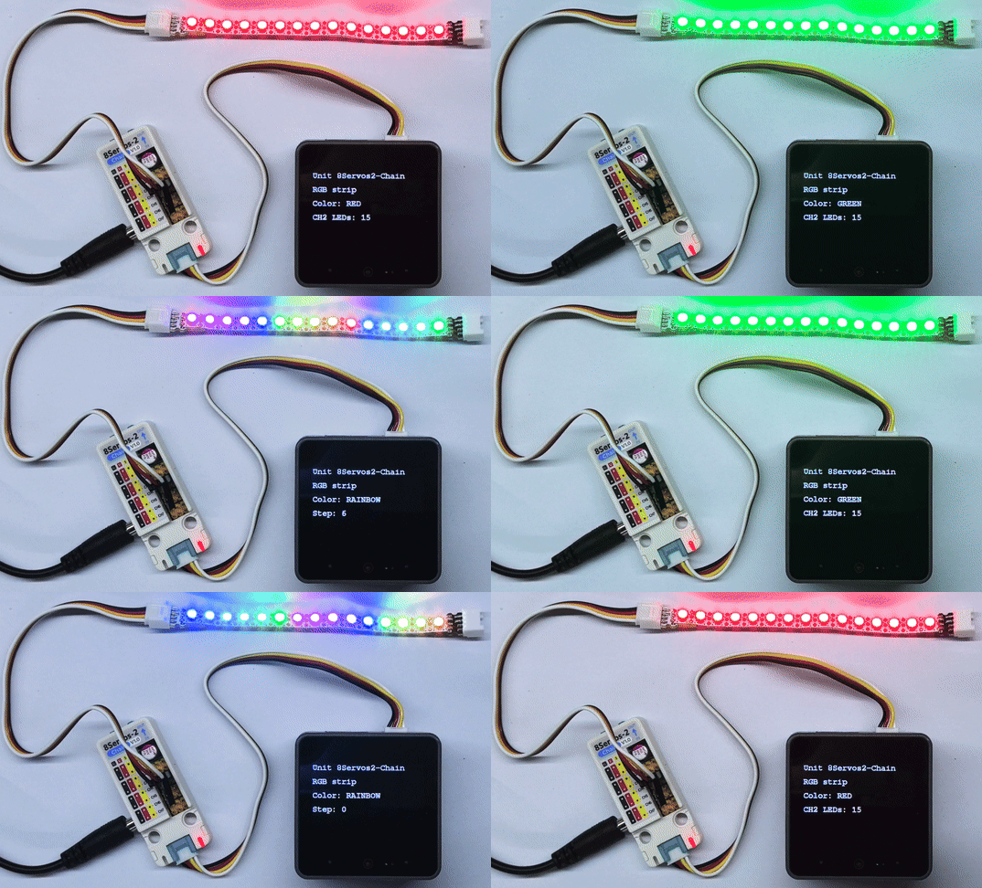
}程序启动后,将 CH2 设置为 RGB 灯带控制通道,并配置 15 颗 RGB LED。灯带依次显示红、绿、蓝,每种颜色持续 500ms;随后以较快的速度连续滚动显示彩虹效果,彩虹动画持续 1 秒。CoreS3 屏幕显示当前颜色,以及灯珠数量或彩虹滚动步数;串口输出红、绿、蓝三种固定颜色的设置结果,彩虹滚动状态显示在屏幕上。
4. 编译上传
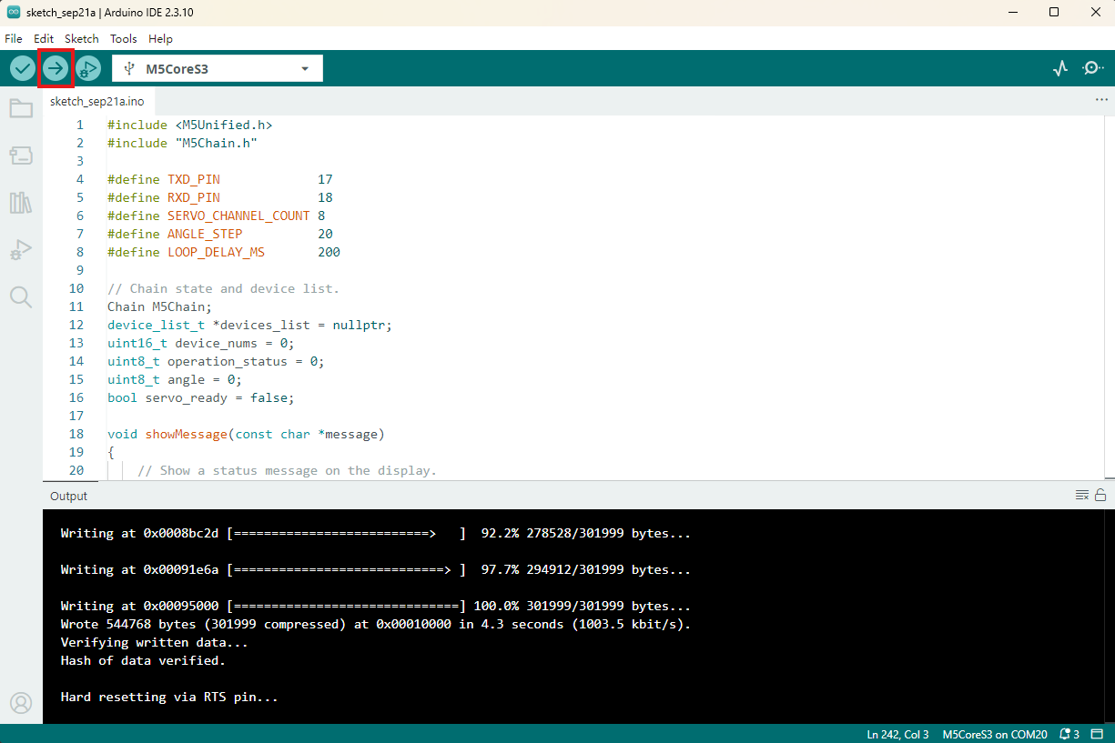
- 复制粘贴上述例程代码到项目代码区,选中设备端口(详情请参考 程序编译与烧录),点击 Arduino IDE 左上角编译上传按钮,等待程序完成编译并上传至设备。