

Arduino 上手教程
2. 设备开发 & 案例程序
3. M5Unified
4. M5GFX
5. 扩展模块
Unit
Module
Atomic
Tab5
IoT
Unit 8Servos2-I2C Arduino 使用教程
1. 准备工作
环境配置:参考 Arduino IDE 上手教程 完成 IDE 安装,并根据实际使用的开发板安装对应的板管理与驱动库。
使用到的驱动库:
使用到的硬件产品:

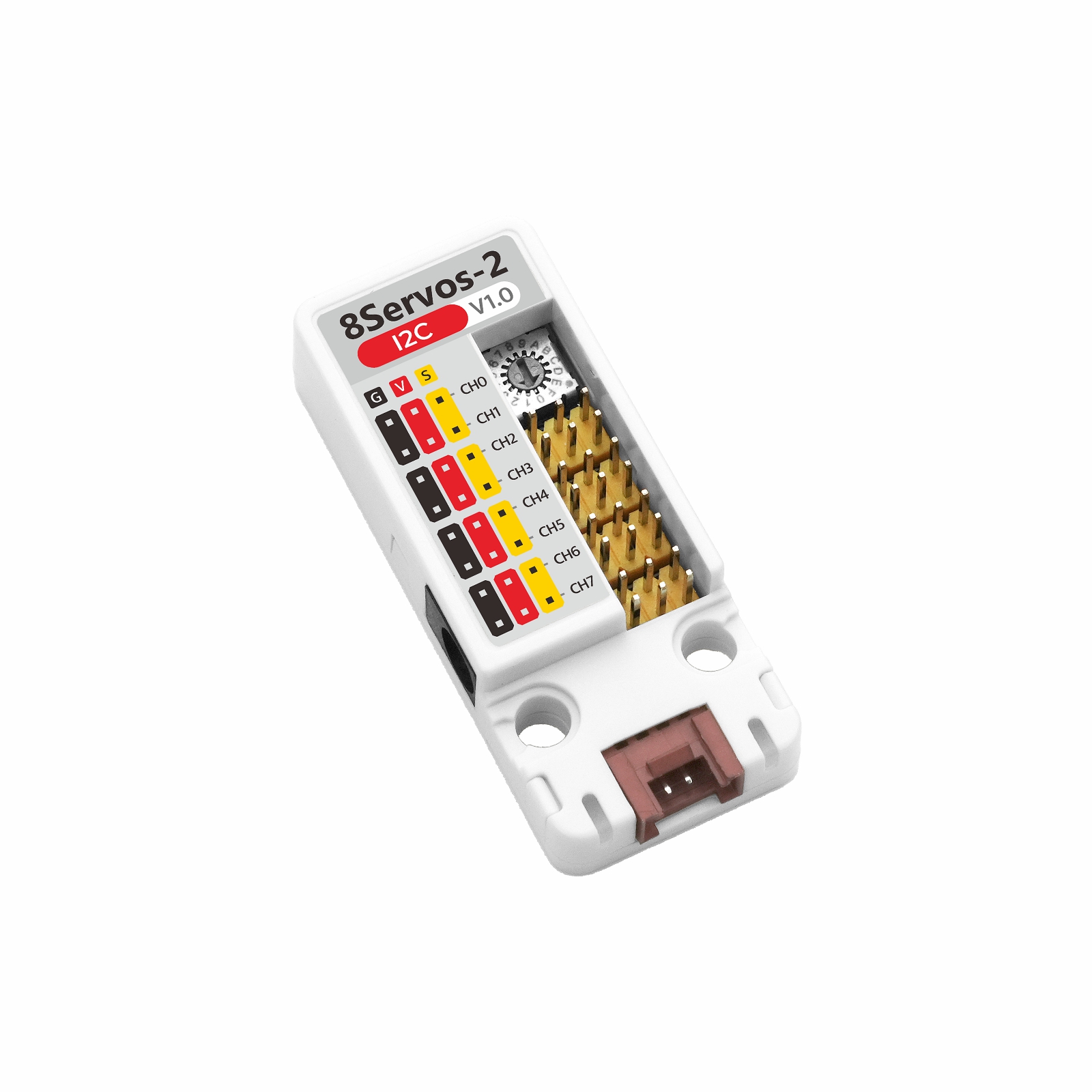
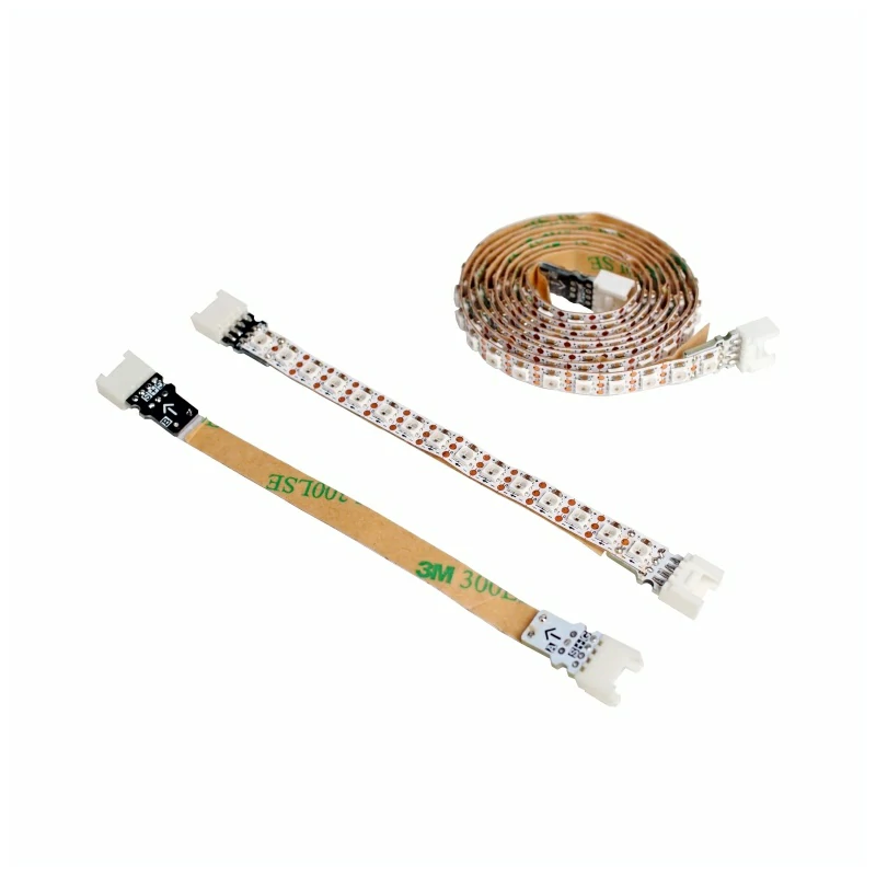
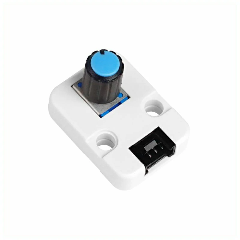
2. 注意事项
引脚兼容性
由于每款主机的引脚配置不同,为了让用户更方便地使用,M5Stack 官方提供了引脚兼容性表,方便用户查看,请根据实际引脚连接情况修改案例程序。
3. 案例程序
- 本教程中使用的主控设备为 CoreS3,搭配 Unit 8Servos2-I2C 控制舵机。Unit 8Servos2-I2C 采用 I2C 协议通信,设备连接后对应的引脚为
G2 (SDA)、G1 (SCL)。
I2C 地址
Unit 8Servos2-I2C 默认 I2C 地址为
0x25,对应 Unit 8Servos2-I2C 上的地址旋钮设置为 0;
如果旋钮设置为其他位置,请将程序中的 UNIT_I2C_ADDRESS 修改为对应地址。说明
下方例程中关闭了 CoreS3 的 5V 输出,若想正常实现功能请接上 Unit 8Servos2-Chain 的外部 DC 电源。若要使用 CoreS3 的 5V 输出,请在
setup() 中将 cfg.output_power 设置为 true。3.1 舵机控制
cpp
1 2 3 4 5 6 7 8 9 10 11 12 13 14 15 16 17 18 19 20 21 22 23 24 25 26 27 28 29 30 31 32 33 34 35 36 37 38 39 40 41 42 43 44 45 46 47 48 49 50 51 52 53 54 55 56 57 58 59 60 61 62 63 64 65 66 67 68 69 70 71 72 73 74 75 76 77 78 79 80 81 82 83 84 85 86 87 88 89 90 91 92 93 94 95 96 97 98 99 100 101
#include <M5Unified.h>
#include <M5Unit8Servos2.h>

constexpr int I2C_SDA_PIN             = 2;
constexpr int I2C_SCL_PIN             = 1;
constexpr uint8_t UNIT_I2C_ADDRESS    = UNIT_8SERVOS2_DEFAULT_ADDR;
constexpr uint8_t SERVO_CHANNEL_COUNT = 8;
constexpr uint32_t I2C_FREQUENCY      = 400000;
constexpr int16_t STATUS_LINE_HEIGHT  = 40;

// Store the Unit controller and current servo position.
M5Unit8Servos2 servos2;
M5Canvas canvas(&M5.Display);
int16_t angle     = 0;
int8_t angle_step = 20;

// Refresh the display with servo and power data.
void drawStatus(uint16_t dc_voltage, uint16_t grove_voltage, uint16_t current_mA)
{
    canvas.fillScreen(TFT_BLACK);
    canvas.setCursor(0, 0);
    canvas.printf("Unit 8Servos2-I2C\n");
    canvas.setCursor(0, STATUS_LINE_HEIGHT);
    canvas.printf("Angle: %d deg", angle);
    canvas.setCursor(0, STATUS_LINE_HEIGHT * 2);
    canvas.printf("DC: %umV", static_cast<unsigned>(dc_voltage));
    canvas.setCursor(0, STATUS_LINE_HEIGHT * 3);
    canvas.printf("Current: %umA", static_cast<unsigned>(current_mA));
    canvas.setCursor(0, STATUS_LINE_HEIGHT * 4);
    canvas.printf("Grove: %umV", static_cast<unsigned>(grove_voltage));
    canvas.pushSprite(0, 0);
}

void setup()
{
    auto cfg = M5.config();
    cfg.output_power = false;
    M5.begin(cfg);
    canvas.createSprite(M5.Display.width(), M5.Display.height());
    Serial.begin(115200);
    canvas.setFont(&fonts::FreeMonoBold12pt7b);
    canvas.setTextColor(TFT_WHITE, TFT_BLACK);

    Wire.begin(I2C_SDA_PIN, I2C_SCL_PIN, I2C_FREQUENCY);
    while (!servos2.begin(&Wire, UNIT_I2C_ADDRESS, -1, -1, I2C_FREQUENCY)) {
        Serial.println("Unit 8Servos2-I2C not found");
        canvas.fillScreen(TFT_BLACK);
        canvas.setCursor(0, 0);
        canvas.printf("Unit not found");
        canvas.setCursor(0, STATUS_LINE_HEIGHT);
        canvas.printf("Check I2C and address");
        canvas.pushSprite(0, 0);
        delay(1000);
    }

    // Set all channels to servo mode.
    for (uint8_t channel = 0; channel < SERVO_CHANNEL_COUNT; ++channel) {
        servos2.setMode(channel, M5_8SERVOS2_MODE_SERVO);
    }

    // Set both PWM timers to 50 Hz for standard servos.
    servos2.setTimerFrequency(0, 50);
    servos2.setTimerFrequency(1, 50);

    // Read the initial power telemetry.
    const uint16_t dc_voltage    = servos2.getDCVoltage();
    const uint16_t grove_voltage = servos2.getGroveVoltage();
    const uint16_t current_mA    = servos2.getSysCurrent();
    Serial.println("Unit 8Servos2-I2C ready");
    drawStatus(dc_voltage, grove_voltage, current_mA);
}

void loop()
{
    // Apply the current angle to all servo channels.
    for (uint8_t channel = 0; channel < SERVO_CHANNEL_COUNT; ++channel) {
        servos2.setServoAngle(channel, static_cast<uint8_t>(angle));
    }

    // Read and report the latest power telemetry.
    const uint16_t dc_voltage    = servos2.getDCVoltage();
    const uint16_t grove_voltage = servos2.getGroveVoltage();
    const uint16_t current_mA    = servos2.getSysCurrent();
    Serial.printf(
        "Servo angle: %d deg, DC: %u mV, Grove: %u mV, Current: %u mA\n", angle,
        static_cast<unsigned>(dc_voltage), static_cast<unsigned>(grove_voltage),
        static_cast<unsigned>(current_mA));
    drawStatus(dc_voltage, grove_voltage, current_mA);

    // Sweep the servos between 0 and 180 degrees.
    angle += angle_step;
    if (angle >= 180) {
        angle      = 180;
        angle_step = -20;
    } else if (angle <= 0) {
        angle      = 0;
        angle_step = 20;
    }

    delay(200);
}程序启动后,将 8 个通道设置为舵机模式,并以 50Hz 控制舵机,舵机以 20° 为步进,在 0° ~ 180° 之间同步往复运动。屏幕显示当前角度、DC 输入电压、系统总电流和 Grove 接口电压,串口输出相同数据。
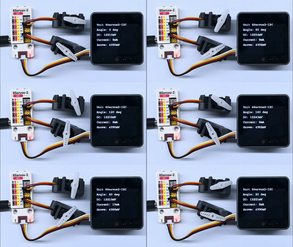
串口返回信息示例如下:
Unit 8Servos2-I2C ready
Servo angle: 0 deg, DC: 12298 mV, Grove: 5024 mV, Current: 8 mA
Servo angle: 20 deg, DC: 12309 mV, Grove: 5026 mV, Current: 8 mA
Servo angle: 40 deg, DC: 12298 mV, Grove: 5024 mV, Current: 8 mA
Servo angle: 60 deg, DC: 12298 mV, Grove: 5024 mV, Current: 8 mA
Servo angle: 80 deg, DC: 12298 mV, Grove: 5024 mV, Current: 8 mA
Servo angle: 100 deg, DC: 12298 mV, Grove: 5024 mV, Current: 6 mA
Servo angle: 120 deg, DC: 12298 mV, Grove: 5030 mV, Current: 8 mA
Servo angle: 140 deg, DC: 12287 mV, Grove: 5022 mV, Current: 8 mA
Servo angle: 160 deg, DC: 12298 mV, Grove: 5028 mV, Current: 8 mA
Servo angle: 180 deg, DC: 12298 mV, Grove: 5030 mV, Current: 8 mA3.2 输入、输出控制
cpp
1 2 3 4 5 6 7 8 9 10 11 12 13 14 15 16 17 18 19 20 21 22 23 24 25 26 27 28 29 30 31 32 33 34 35 36 37 38 39 40 41 42 43 44 45 46 47 48 49 50 51 52 53 54 55 56 57 58 59 60 61 62 63 64 65 66 67 68 69 70 71 72 73 74 75 76 77 78
#include <M5Unified.h>
#include <M5Unit8Servos2.h>

constexpr int I2C_SDA_PIN             = 2;
constexpr int I2C_SCL_PIN             = 1;
constexpr uint8_t UNIT_I2C_ADDRESS    = UNIT_8SERVOS2_DEFAULT_ADDR;
constexpr uint32_t I2C_FREQUENCY      = 400000;
constexpr int16_t STATUS_LINE_HEIGHT  = 40;

M5Unit8Servos2 servos2;
M5Canvas canvas(&M5.Display);
bool output_ch0 = false;
bool output_ch4 = true;

void drawStatus(bool input_ch3, bool input_ch7)
{
    canvas.fillScreen(TFT_BLACK);
    canvas.setCursor(0, 0);
    canvas.printf("Unit 8Servos2-I2C\n");
    canvas.setCursor(0, STATUS_LINE_HEIGHT);
    canvas.printf("CH0 OUT: %s", output_ch0 ? "HIGH" : "LOW");
    canvas.setCursor(0, STATUS_LINE_HEIGHT * 2);
    canvas.printf("CH4 OUT: %s", output_ch4 ? "HIGH" : "LOW");
    canvas.setCursor(0, STATUS_LINE_HEIGHT * 3);
    canvas.printf("CH3 IN:  %s", input_ch3 ? "HIGH" : "LOW");
    canvas.setCursor(0, STATUS_LINE_HEIGHT * 4);
    canvas.printf("CH7 IN:  %s", input_ch7 ? "HIGH" : "LOW");
    canvas.pushSprite(0, 0);
}

void setup()
{
    auto cfg = M5.config();
    cfg.output_power = false;
    M5.begin(cfg);
    canvas.createSprite(M5.Display.width(), M5.Display.height());
    Serial.begin(115200);
    canvas.setFont(&fonts::FreeMonoBold12pt7b);
    canvas.setTextColor(TFT_WHITE, TFT_BLACK);

    Wire.begin(I2C_SDA_PIN, I2C_SCL_PIN, I2C_FREQUENCY);
    while (!servos2.begin(&Wire, UNIT_I2C_ADDRESS, -1, -1, I2C_FREQUENCY)) {
        Serial.println("Unit 8Servos2-I2C not found");
        canvas.fillScreen(TFT_BLACK);
        canvas.setCursor(0, 0);
        canvas.printf("Unit not found");
        canvas.setCursor(0, STATUS_LINE_HEIGHT);
        canvas.printf("Check I2C and address");
        canvas.pushSprite(0, 0);
        delay(1000);
    }

    // Configure output and input channels.
    servos2.setMode(0, M5_8SERVOS2_MODE_OUTPUT);
    servos2.setMode(4, M5_8SERVOS2_MODE_OUTPUT);
    servos2.setMode(3, M5_8SERVOS2_MODE_INPUT);
    servos2.setMode(7, M5_8SERVOS2_MODE_INPUT);
    servos2.setInputPull(3, M5_8SERVOS2_PULL_UP);
    servos2.setInputPull(7, M5_8SERVOS2_PULL_UP);
}

void loop()
{
    // Set opposite output levels and read the input levels.
    servos2.setDigitalOutput(0, output_ch0);
    servos2.setDigitalOutput(4, output_ch4);
    const bool input_ch3 = servos2.getDigitalInput(3);
    const bool input_ch7 = servos2.getDigitalInput(7);

    Serial.printf("CH0: %s, CH4: %s, CH3: %s, CH7: %s\n",
                  output_ch0 ? "HIGH" : "LOW", output_ch4 ? "HIGH" : "LOW",
                  input_ch3 ? "HIGH" : "LOW", input_ch7 ? "HIGH" : "LOW");
    drawStatus(input_ch3, input_ch7);

    output_ch0 = !output_ch0;
    output_ch4 = !output_ch0;
    delay(500);
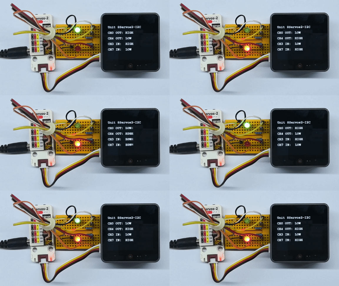
}连接至 CH0 和 CH4 的外接 LED 灯珠会交替亮灭,两个通道的灯光状态相反,约每 500ms 切换一次。演示时将 CH3、CH7 分别外接至 CH0、CH4,读取对应的高低电平;屏幕和串口同步显示两路输出状态和两路输入电平。
3.3 ADC 采集
cpp
1 2 3 4 5 6 7 8 9 10 11 12 13 14 15 16 17 18 19 20 21 22 23 24 25 26 27 28 29 30 31 32 33 34 35 36 37 38 39 40 41 42 43 44 45 46 47 48 49 50 51 52 53 54 55 56 57 58 59 60 61 62
#include <M5Unified.h>
#include <M5Unit8Servos2.h>

constexpr int I2C_SDA_PIN             = 2;
constexpr int I2C_SCL_PIN             = 1;
constexpr uint8_t UNIT_I2C_ADDRESS    = UNIT_8SERVOS2_DEFAULT_ADDR;
constexpr uint32_t I2C_FREQUENCY      = 400000;
constexpr int16_t STATUS_LINE_HEIGHT  = 40;

M5Unit8Servos2 servos2;
M5Canvas canvas(&M5.Display);

void drawStatus(uint16_t adc_raw, uint16_t voltage_mV)
{
    canvas.fillScreen(TFT_BLACK);
    canvas.setCursor(0, 0);
    canvas.printf("Unit 8Servos2-I2C\n");
    canvas.setCursor(0, STATUS_LINE_HEIGHT);
    canvas.printf("Channel: CH4");
    canvas.setCursor(0, STATUS_LINE_HEIGHT * 2);
    canvas.printf("ADC Raw: %u", static_cast<unsigned>(adc_raw));
    canvas.setCursor(0, STATUS_LINE_HEIGHT * 3);
    canvas.printf("Voltage: %umV", static_cast<unsigned>(voltage_mV));
    canvas.pushSprite(0, 0);
}

void setup()
{
    auto cfg = M5.config();
    cfg.output_power = false;
    M5.begin(cfg);
    canvas.createSprite(M5.Display.width(), M5.Display.height());
    Serial.begin(115200);
    canvas.setFont(&fonts::FreeMonoBold12pt7b);
    canvas.setTextColor(TFT_WHITE, TFT_BLACK);

    Wire.begin(I2C_SDA_PIN, I2C_SCL_PIN, I2C_FREQUENCY);
    while (!servos2.begin(&Wire, UNIT_I2C_ADDRESS, -1, -1, I2C_FREQUENCY)) {
        Serial.println("Unit 8Servos2-I2C not found");
        canvas.fillScreen(TFT_BLACK);
        canvas.setCursor(0, 0);
        canvas.printf("Unit not found");
        canvas.setCursor(0, STATUS_LINE_HEIGHT);
        canvas.printf("Check I2C and address");
        canvas.pushSprite(0, 0);
        delay(1000);
    }

    // Configure CH4 for ADC input.
    servos2.setMode(4, M5_8SERVOS2_MODE_ADC);
}

void loop()
{
    // Read the latest raw ADC value and voltage.
    const uint16_t adc_raw    = servos2.getADCRaw(4);
    const uint16_t voltage_mV = servos2.getVoltageMV(4);
    Serial.printf("CH4 ADC: %u, Voltage: %umV\n", static_cast<unsigned>(adc_raw),
                  static_cast<unsigned>(voltage_mV));
    drawStatus(adc_raw, voltage_mV);
    delay(200);
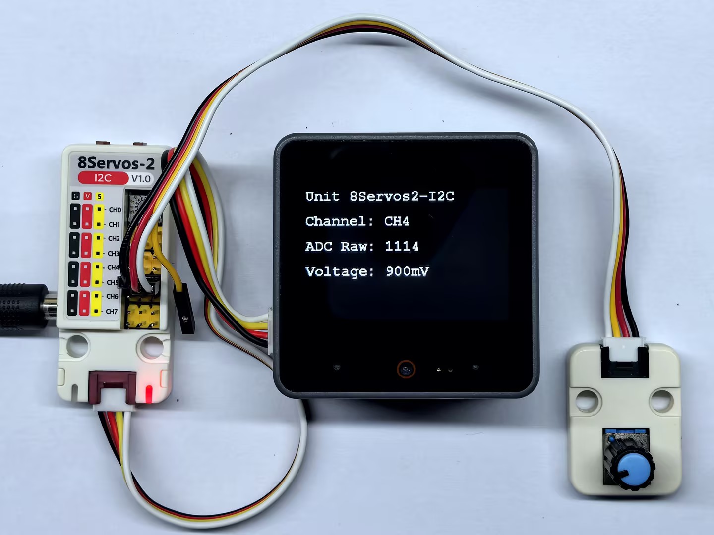
}程序启动后,将 CH4 设置为 ADC 模式,持续读取 ADC 原始值和换算后的电压值。CoreS3 屏幕显示 CH4 的 ADC 值和电压,串口同步输出采集结果。
3.4 PWM 输出
cpp
1 2 3 4 5 6 7 8 9 10 11 12 13 14 15 16 17 18 19 20 21 22 23 24 25 26 27 28 29 30 31 32 33 34 35 36 37 38 39 40 41 42 43 44 45 46 47 48 49 50 51 52 53 54 55 56 57 58 59 60 61 62 63 64 65 66 67 68 69 70 71 72 73 74 75 76 77
#include <M5Unified.h>
#include <M5Unit8Servos2.h>

constexpr int I2C_SDA_PIN             = 2;
constexpr int I2C_SCL_PIN             = 1;
constexpr uint8_t UNIT_I2C_ADDRESS    = UNIT_8SERVOS2_DEFAULT_ADDR;
constexpr uint32_t I2C_FREQUENCY      = 400000;
constexpr uint16_t PWM_FREQUENCY      = 1000;
constexpr int16_t STATUS_LINE_HEIGHT  = 40;

M5Unit8Servos2 servos2;
M5Canvas canvas(&M5.Display);
uint8_t duty_ch0 = 0;
uint8_t duty_ch4 = 100;
int8_t duty_step = 10;

void drawStatus()
{
    canvas.fillScreen(TFT_BLACK);
    canvas.setCursor(0, 0);
    canvas.printf("Unit 8Servos2-I2C\n");
    canvas.setCursor(0, STATUS_LINE_HEIGHT);
    canvas.printf("CH0: %u%%", static_cast<unsigned>(duty_ch0));
    canvas.setCursor(0, STATUS_LINE_HEIGHT * 2);
    canvas.printf("CH4: %u%%", static_cast<unsigned>(duty_ch4));
    canvas.setCursor(0, STATUS_LINE_HEIGHT * 3);
    canvas.printf("Frequency: %uHz", static_cast<unsigned>(PWM_FREQUENCY));
    canvas.pushSprite(0, 0);
}

void setup()
{
    auto cfg = M5.config();
    cfg.output_power = false;
    M5.begin(cfg);
    canvas.createSprite(M5.Display.width(), M5.Display.height());
    Serial.begin(115200);
    canvas.setFont(&fonts::FreeMonoBold12pt7b);
    canvas.setTextColor(TFT_WHITE, TFT_BLACK);

    Wire.begin(I2C_SDA_PIN, I2C_SCL_PIN, I2C_FREQUENCY);
    while (!servos2.begin(&Wire, UNIT_I2C_ADDRESS, -1, -1, I2C_FREQUENCY)) {
        Serial.println("Unit 8Servos2-I2C not found");
        canvas.fillScreen(TFT_BLACK);
        canvas.setCursor(0, 0);
        canvas.printf("Unit not found");
        canvas.setCursor(0, STATUS_LINE_HEIGHT);
        canvas.printf("Check I2C and address");
        canvas.pushSprite(0, 0);
        delay(1000);
    }

    // Configure CH0 and CH4 for PWM output.
    servos2.setMode(0, M5_8SERVOS2_MODE_PWM);
    servos2.setMode(4, M5_8SERVOS2_MODE_PWM);
    servos2.setTimerFrequency(0, PWM_FREQUENCY);
    servos2.setTimerFrequency(1, PWM_FREQUENCY);
}

void loop()
{
    // Apply opposite duty cycles to CH0 and CH4.
    servos2.setPWMDuty(0, duty_ch0);
    servos2.setPWMDuty(4, duty_ch4);
    Serial.printf("CH0: %u%%, CH4: %u%%\n", static_cast<unsigned>(duty_ch0),
                  static_cast<unsigned>(duty_ch4));
    drawStatus();

    if (duty_ch0 >= 100) {
        duty_step = -10;
    } else if (duty_ch0 == 0) {
        duty_step = 10;
    }
    duty_ch0 = static_cast<uint8_t>(duty_ch0 + duty_step);
    duty_ch4 = 100 - duty_ch0;
    delay(50);
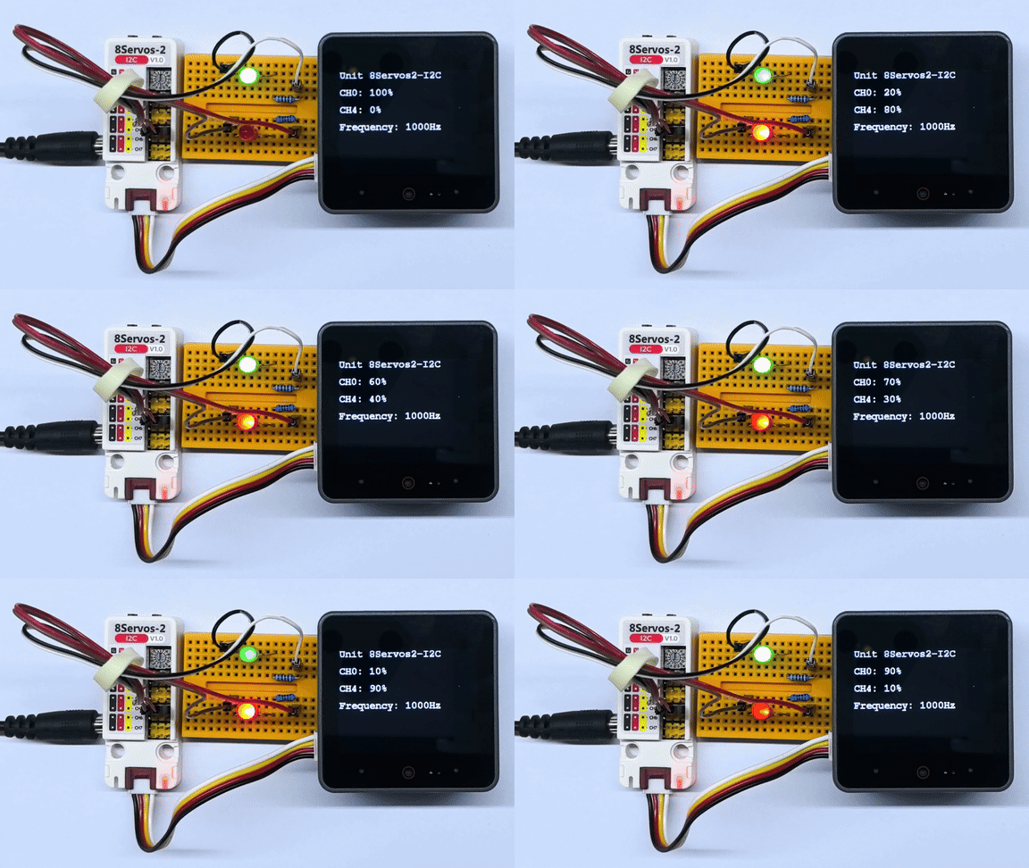
}连接至 CH0 和 CH4 的外接 LED 灯珠会呈现此消彼长的明暗变化:一路灯光逐渐变亮时,另一路逐渐变暗;达到最亮或熄灭状态后,亮度变化方向反转。灯光约每 50ms 更新一次,屏幕显示两路占空比和 1000Hz 输出频率,串口输出两路占空比。
3.5 RGB 灯控制
cpp
1 2 3 4 5 6 7 8 9 10 11 12 13 14 15 16 17 18 19 20 21 22 23 24 25 26 27 28 29 30 31 32 33 34 35 36 37 38 39 40 41 42 43 44 45 46 47 48 49 50 51 52 53 54 55 56 57 58 59 60 61 62 63 64 65 66 67 68 69 70 71 72 73 74 75 76 77 78 79 80 81 82 83 84 85 86 87 88 89 90 91 92 93 94 95 96 97 98 99 100 101 102 103 104 105 106 107 108 109 110 111 112 113 114 115 116 117 118 119 120 121 122 123 124 125 126 127
#include <M5Unified.h>
#include <M5Unit8Servos2.h>

constexpr int I2C_SDA_PIN             = 2;
constexpr int I2C_SCL_PIN             = 1;
constexpr uint8_t UNIT_I2C_ADDRESS    = UNIT_8SERVOS2_DEFAULT_ADDR;
constexpr uint8_t RGB_CHANNEL         = 2;
constexpr uint8_t RGB_LED_COUNT       = 15;
constexpr uint8_t RGB_BRIGHTNESS_PERCENT = 5;
constexpr uint32_t I2C_FREQUENCY      = 400000;
constexpr int16_t STATUS_LINE_HEIGHT  = 40;

M5Unit8Servos2 servos2;
M5Canvas canvas(&M5.Display);

uint32_t colorWheel(uint8_t position)
{
    position = 255 - position;
    if (position < 85) {
        return ((255 - position * 3) << 16) | (position * 3);
    }
    if (position < 170) {
        position -= 85;
        return (position * 3 << 8) | (255 - position * 3);
    }
    position -= 170;
    return (position * 3 << 16) | (255 - position * 3 << 8);
}

void showStatus(const char *mode)
{
    canvas.fillScreen(TFT_BLACK);
    canvas.setCursor(0, 0);
    canvas.printf("Unit 8Servos2-I2C\n");
    canvas.setCursor(0, STATUS_LINE_HEIGHT);
    canvas.printf("Channel: CH2");
    canvas.setCursor(0, STATUS_LINE_HEIGHT * 2);
    canvas.printf("Mode: %s", mode);
    canvas.setCursor(0, STATUS_LINE_HEIGHT * 3);
    canvas.printf("LEDs: %u", static_cast<unsigned>(RGB_LED_COUNT));
    canvas.setCursor(0, STATUS_LINE_HEIGHT * 4);
    canvas.printf("Brightness: %u%%", static_cast<unsigned>(RGB_BRIGHTNESS_PERCENT));
    canvas.pushSprite(0, 0);
}

// Scale each RGB component before writing the buffer.
uint32_t applyBrightness(uint32_t color)
{
    const uint8_t red   = (color >> 16) & 0xFF;
    const uint8_t green = (color >> 8) & 0xFF;
    const uint8_t blue  = color & 0xFF;
    return ((red * RGB_BRIGHTNESS_PERCENT / 100) << 16) |
           ((green * RGB_BRIGHTNESS_PERCENT / 100) << 8) |
           (blue * RGB_BRIGHTNESS_PERCENT / 100);
}

void setSolidColor(uint32_t color)
{
    uint32_t colors[RGB_LED_COUNT] = {0};
    for (uint8_t i = 0; i < RGB_LED_COUNT; ++i) {
        colors[i] = applyBrightness(color);
    }
    servos2.setRGBBuffer(colors, RGB_LED_COUNT);
    servos2.setRGBConfig(RGB_CHANNEL, RGB_LED_COUNT, true);
}

void setRainbow(uint8_t offset)
{
    uint32_t colors[RGB_LED_COUNT] = {0};
    for (uint8_t i = 0; i < RGB_LED_COUNT; ++i) {
        const uint8_t position = static_cast<uint8_t>(
            (static_cast<uint16_t>(i) * 256 / RGB_LED_COUNT + 256 - offset) & 0xFF);
        colors[i] = applyBrightness(colorWheel(position));
    }
    servos2.setRGBBuffer(colors, RGB_LED_COUNT);
    servos2.setRGBConfig(RGB_CHANNEL, RGB_LED_COUNT, true);
}

void setup()
{
    auto cfg = M5.config();
    M5.begin(cfg);
    canvas.createSprite(M5.Display.width(), M5.Display.height());
    Serial.begin(115200);
    canvas.setFont(&fonts::FreeMonoBold12pt7b);
    canvas.setTextColor(TFT_WHITE, TFT_BLACK);

    Wire.begin(I2C_SDA_PIN, I2C_SCL_PIN, I2C_FREQUENCY);
    while (!servos2.begin(&Wire, UNIT_I2C_ADDRESS, -1, -1, I2C_FREQUENCY)) {
        Serial.println("Unit 8Servos2-I2C not found");
        canvas.fillScreen(TFT_BLACK);
        canvas.setCursor(0, 0);
        canvas.printf("Unit not found");
        canvas.setCursor(0, STATUS_LINE_HEIGHT);
        canvas.printf("Check I2C and address");
        canvas.pushSprite(0, 0);
        delay(1000);
    }

    // Configure CH2 for RGB strip control.
    servos2.setMode(RGB_CHANNEL, M5_8SERVOS2_MODE_RGB);
}

void loop()
{
    const uint32_t solid_colors[] = {0xFF0000, 0x00FF00, 0x0000FF};
    const char *solid_names[]     = {"Red", "Green", "Blue"};

    // Show red, green, and blue for 200 ms each.
    for (uint8_t i = 0; i < 3; ++i) {
        setSolidColor(solid_colors[i]);
        showStatus(solid_names[i]);
        Serial.printf("CH2 RGB: %s, Brightness: %u%%\n", solid_names[i],
                      static_cast<unsigned>(RGB_BRIGHTNESS_PERCENT));
        delay(200);
    }

    // Scroll a rainbow pattern continuously for 1 second.
    const uint32_t rainbow_start = millis();
    uint8_t rainbow_offset        = 0;
    while (millis() - rainbow_start < 1000) {
        setRainbow(rainbow_offset);
        showStatus("Rainbow");
        rainbow_offset += 16;
        delay(20);
    }
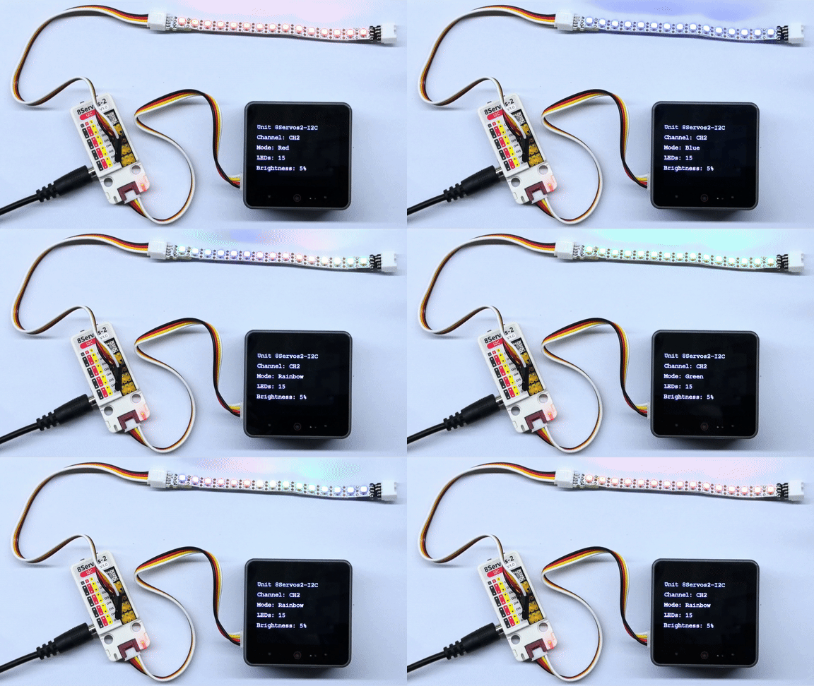
}CH2 上的 15 颗 RGB LED 依次显示红、绿、蓝,每种颜色保持约 200ms;随后彩虹色从第 1 颗向第 15 颗滚动,约每 20ms 更新一次,持续约 1 秒后循环。所有颜色的 RGB 分量均按 5% 缩放。CoreS3 屏幕显示通道、模式、灯珠数量和亮度设置;串口仅在红、绿、蓝阶段输出颜色名称和亮度设置。
4. 编译上传
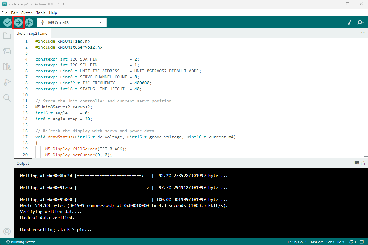
- 复制粘贴上述例程代码到项目代码区,选中设备端口(详情请参考 程序编译与烧录),点击 Arduino IDE 左上角编译上传按钮,等待程序完成编译并上传至设备。
Page Tools