

Arduino 上手教程
2. 设备开发 & 案例程序
3. M5Unified
4. M5GFX
5. 扩展模块
Unit
Module
Atomic
Tab5
IoT
Module13.2 LoRa-1262 Arduino 使用教程
1. 准备工作
- 环境配置: 参考 Arduino IDE 上手教程完成 IDE 安装,并根据实际使用的开发板安装对应的板管理,与需要的驱动库。
- 使用到的驱动库:
- 使用到的硬件产品:


2. 注意事项
天线连接
使用 LoRa 模块前请先连接匹配的外置天线,禁止在未连接天线的情况下进行发射,否则设备硬件可能会永久损坏。
I2C 地址
模块可通过 SW2 的 A、B 拨码开关设置 IO 扩展芯片地址,地址表如下。
| A | B | I2C 地址 |
|---|---|---|
| 0 | 0 | 0x74 |
| 1 | 0 | 0x73 |
| 0 | 1 | 0x72 |
| 1 | 1 | 0x71 |
引脚兼容性
由于每款主机的引脚配置不同,为了让用户更方便地使用,M5Stack 官方提供了引脚兼容性表,方便用户查看,请根据实际引脚连接情况修改案例程序。
3. 案例程序
- 本教程中使用的主控设备为 CoreS3,搭配 Module13.2 LoRa-1262 实现无线通信。使用前请参考下图,将引脚拨码开关,切换到指定位置。
3.1 引脚拨码开关
- Module13.2 LoRa-1262 采用 SPI 的方式通讯,请根据实际的电路连接修改程序中的引脚定义,设备连接 CoreS3 后对应的 SPI IO 为
G1 (NSS)、G2 (BUSY)、G37 (MOSI)、G35 (MISO)、G36 (SCK),中断 IO 为G10 (IRQ),IO 扩展芯片地址为实物如下图所示:

3.2 参数配置
Module13.2 LoRa-1262 支持多种参数配置,使用前请参考下方内容进行设置,若需各项参数的含义及其他详细信息请见数据手册,并根据实际需求调整案例程序中的参数设置,确保发送端与接收端参数一致。
频率 (LORA_FREQ)
- Module13.2 LoRa-1262 支持
868 ~ 923 MHz频段,请根据使用地区的无线电法规选择频率。 - 发送端和接收端必须使用相同的频率。
带宽 (LORA_BW)
- 单位为 kHz,带宽越小,通常接收灵敏度和远距离通信能力越好,但数据速率越低、数据包占用时间越长;带宽越大,数据速率越高,但抗噪声能力和通信距离可能降低。
扩频因子 (LORA_SF)
- 可设置范围为 6 ~ 12。
- 数值越大,接收灵敏度和抗干扰能力通常越好,但传输速率越低、数据包占用时间越长。
- 发送端和接收端必须使用相同的扩频因子。
编码率 (LORA_CR)
- 可设置范围为 5 ~ 8,分别对应编码率
4/5~4/8。 - 数值越大,纠错能力越强,但有效数据速率越低、数据包占用时间越长。
同步字 (LORA_SYNC_WORD)
- 用于区分不同的 LoRa 网络。
- 只有同步字一致时,接收端才能正常识别对应的数据包,发送端和接收端必须使用相同的同步字。
发送功率 (LORA_TX_POWER)
- 可设置范围为 -9 ~ 22 dBm。
- 数值越大,发送功率通常越高、通信距离越远,但功耗和对电源的要求也会增加。
注意:
1. 若不能使用稳定电源供电,如使用 CoreS3 电池底座,请设置较低功率值,否则模组将不能正常工作。
2. 此参数对接收端无实际意义,仅用于使软件成功编译。
2. 此参数对接收端无实际意义,仅用于使软件成功编译。
前导码长度 (LORA_PREAMBLE_LEN)
- 前导码用于帮助接收端检测数据包的开始,适当增加长度有助于弱信号接收,但会增加数据包占用时间。
- 发送端和接收端应使用相同的设置。
说明
下方代码中只设置了
NSS、IRQ、BUSY 三个引脚,但实际上 RadioLib 库会根据所使用的主控设备,自动映射剩余的 SPI 引脚 (MOSI、MISO、SCK),即使用 M5Unified 库初始化时根据不同设备默认定义的引脚,因此无需手动指定。3.3 发送端
cpp
1 2 3 4 5 6 7 8 9 10 11 12 13 14 15 16 17 18 19 20 21 22 23 24 25 26 27 28 29 30 31 32 33 34 35 36 37 38 39 40 41 42 43 44 45 46 47 48 49 50 51 52 53 54 55 56 57 58 59 60 61 62 63 64 65 66 67 68 69 70 71 72 73 74 75 76 77 78 79 80 81 82 83 84 85 86 87 88 89 90 91 92 93 94 95 96 97 98 99 100 101 102 103 104 105 106 107 108 109 110 111 112 113 114 115 116 117 118 119 120 121 122 123 124 125 126 127 128 129 130 131 132 133 134 135 136 137 138 139 140 141 142 143 144 145 146 147 148 149 150 151 152 153 154 155 156 157 158 159 160 161 162 163 164 165 166 167 168 169 170 171 172 173 174 175 176 177 178 179 180 181 182 183 184 185 186 187 188 189 190 191 192 193 194
#include <M5Unified.h>
#include <M5IOE1.h>
#include <RadioLib.h>

// M5IOE1 I2C address selected by SW2.
#define IO_EXPANDER_ADDRESS 0x74

// CoreS3 pins selected by the module DIP switches.
#define LORA_NSS_PIN  GPIO_NUM_1
#define LORA_BUSY_PIN GPIO_NUM_2
#define LORA_IRQ_PIN  GPIO_NUM_10

// M5IOE1 pins for LoRa reset, bypass, and power control.
#define PY_IO2_LORA_RST   M5IOE1_PIN_2
#define PY_IO3_BYPASS     M5IOE1_PIN_3
#define PY_IO5_PWR_EN     M5IOE1_PIN_5

// LoRa parameters. These values must match on both devices.
#define LORA_FREQ         868.0f  // Carrier frequency (MHz).
#define LORA_BW           125.0f  // Bandwidth (kHz).
#define LORA_SF           12      // Spreading factor.
#define LORA_CR           5       // Coding rate: 4/5.
#define LORA_SYNC_WORD    0x34    // Sync word.
#define LORA_TX_POWER     22      // TX power (dBm).
#define LORA_CURRENT_LIMIT 140.0f // TX current limit (mA).
#define LORA_PREAMBLE_LEN 20      // Preamble length (symbols).

// SX1262 pins: NSS, IRQ, reset (controlled by M5IOE1), and BUSY.
SX1262 radio = new Module(LORA_NSS_PIN, LORA_IRQ_PIN, RADIOLIB_NC, LORA_BUSY_PIN);
M5Canvas canvas(&M5.Lcd);
M5IOE1 ioe1;

int transmissionState = RADIOLIB_ERR_NONE;
volatile bool transmittedFlag = false;

bool setExpanderOutput(uint8_t pin, uint8_t level)
{
    // Configure one M5IOE1 pin as a push-pull output and set its level.
    m5ioe1_err_t error = M5IOE1_OK;
    ioe1.pinModeWithRes(pin, OUTPUT, &error);
    if (error != M5IOE1_OK) {
        return false;
    }
    if (ioe1.setDriveMode(pin, M5IOE1_DRIVE_PUSHPULL) != M5IOE1_OK) {
        return false;
    }
    ioe1.digitalWriteWithRes(pin, level, &error);
    return error == M5IOE1_OK;
}

bool initModuleControl()
{
    // Initialize the M5IOE1 control interface.
    const m5ioe1_err_t ioeState = ioe1.begin(
        &M5.In_I2C, IO_EXPANDER_ADDRESS, M5IOE1_I2C_FREQ_100K,
        M5IOE1_INT_MODE_DISABLED);
    if (ioeState != M5IOE1_OK) {
        Serial.printf("M5IOE1 init failed at 0x%02X, code: %d\n",
                      IO_EXPANDER_ADDRESS, ioeState);
        return false;
    }

    // Hold reset, set the bypass control, and disable module power.
    if (!setExpanderOutput(PY_IO2_LORA_RST, LOW) ||
        !setExpanderOutput(PY_IO3_BYPASS, HIGH) ||
        !setExpanderOutput(PY_IO5_PWR_EN, LOW)) {
        return false;
    }
    delay(25);

    // Enable module power before releasing reset.
    if (!setExpanderOutput(PY_IO5_PWR_EN, HIGH)) {
        return false;
    }
    delay(120);

    // Release reset after the power rail is stable.
    if (!setExpanderOutput(PY_IO2_LORA_RST, HIGH)) {
        return false;
    }
    delay(120);
    return true;
}

void IRAM_ATTR setFlag(void)
{
    // Mark the packet-sent event for loop().
    transmittedFlag = true;
}

void showSending(const String& payload, int count)
{
    canvas.clear();
    canvas.setCursor(0, 5);
    canvas.printf("[SX1262]\nSending #%d packet......\n", count);
    canvas.printf("Data:\n %s\n", payload.c_str());
    canvas.pushSprite(0, 0);
}

void setup()
{
    auto cfg = M5.config();
    M5.begin(cfg);
    Serial.begin(115200);
    canvas.createSprite(320, 240);
    canvas.setFont(&fonts::FreeMonoBold9pt7b);

    if (!initModuleControl()) {
        Serial.println(F("IO_EXP init failed"));
        canvas.println(F("IO_EXP init failed"));
        canvas.pushSprite(0, 0);
        while (true) {
            delay(1000);
        }
    }

    // Initialize the SX1262.
    Serial.print(F("[SX1262] Initializing ... "));
    int state = radio.begin(LORA_FREQ, LORA_BW, LORA_SF, LORA_CR,
                            LORA_SYNC_WORD, LORA_TX_POWER, LORA_PREAMBLE_LEN,
                            3.0f, true);
    if (state != RADIOLIB_ERR_NONE) {
        Serial.print(F("failed, code "));
        Serial.println(state);
        canvas.println(F("SX1262 init failed"));
        canvas.pushSprite(0, 0);
        while (true) {
            delay(1000);
        }
    }
    state = radio.setCurrentLimit(LORA_CURRENT_LIMIT);
    if (state != RADIOLIB_ERR_NONE) {
        Serial.print(F("current limit setup failed, code "));
        Serial.println(state);
        canvas.println(F("Current limit setup failed"));
        canvas.pushSprite(0, 0);
        while (true) {
            delay(1000);
        }
    }
    Serial.println(F("success!"));

    // Register the callback for the packet-sent interrupt.
    radio.setPacketSentAction(setFlag);
    // Send an initial packet to start interrupt-driven transmission.
    Serial.print(F("[SX1262] Sending first packet ... "));
    transmissionState = radio.startTransmit("Transmitter Ready");
    if (transmissionState != RADIOLIB_ERR_NONE) {
        Serial.print(F("startTransmit failed, code: "));
        Serial.println(transmissionState);
    }
    canvas.clear();
    canvas.setCursor(0, 5);
    canvas.println(F("[SX1262]"));
    canvas.println(F("Transmitter Ready"));
    canvas.pushSprite(0, 0);
}

int count = 0;

void loop()
{
    // Wait until the packet-sent interrupt is received.
    if (!transmittedFlag) {
        return;
    }
    transmittedFlag = false;

    if (transmissionState == RADIOLIB_ERR_NONE) {
        Serial.println(F("Transmission finished!"));
        canvas.println(F("Send successfully!"));
        canvas.pushSprite(0, 0);
    } else {
        Serial.print(F("Send failed, code: "));
        Serial.println(transmissionState);
        canvas.println(F("Send failed"));
        canvas.printf("code: %d\n", transmissionState);
        canvas.pushSprite(0, 0);
    }

    // Finish the previous transmission before starting the next one.
    radio.finishTransmit();
    delay(1000);

    // Start the next packet.
    String payload = "Module13.2 LoRa-1262 #" + String(count);
    Serial.printf("[SX1262] Sending #%d packet ... ", count);
    transmissionState = radio.startTransmit(payload);
    if (transmissionState != RADIOLIB_ERR_NONE) {
        Serial.print(F("startTransmit failed, code: "));
        Serial.println(transmissionState);
    }
    showSending(payload, count++);
}3.4 接收端
cpp
1 2 3 4 5 6 7 8 9 10 11 12 13 14 15 16 17 18 19 20 21 22 23 24 25 26 27 28 29 30 31 32 33 34 35 36 37 38 39 40 41 42 43 44 45 46 47 48 49 50 51 52 53 54 55 56 57 58 59 60 61 62 63 64 65 66 67 68 69 70 71 72 73 74 75 76 77 78 79 80 81 82 83 84 85 86 87 88 89 90 91 92 93 94 95 96 97 98 99 100 101 102 103 104 105 106 107 108 109 110 111 112 113 114 115 116 117 118 119 120 121 122 123 124 125 126 127 128 129 130 131 132 133 134 135 136 137 138 139 140 141 142 143 144 145 146 147 148 149 150 151 152 153 154 155 156 157 158 159 160 161 162 163 164 165 166 167 168 169 170 171 172 173 174 175 176 177 178 179 180 181 182 183 184 185 186 187 188 189 190 191 192 193 194 195 196 197 198 199 200 201 202 203 204
#include <M5Unified.h>
#include <M5IOE1.h>
#include <RadioLib.h>

// M5IOE1 I2C address selected by SW2.
#define IO_EXPANDER_ADDRESS 0x74

// CoreS3 pins selected by the module DIP switches.
#define LORA_NSS_PIN  GPIO_NUM_1
#define LORA_BUSY_PIN GPIO_NUM_2
#define LORA_IRQ_PIN  GPIO_NUM_10

// M5IOE1 pins for LoRa reset, bypass, and power control.
#define PY_IO2_LORA_RST   M5IOE1_PIN_2
#define PY_IO3_BYPASS     M5IOE1_PIN_3
#define PY_IO5_PWR_EN     M5IOE1_PIN_5

// LoRa parameters. These values must match on both devices.
#define LORA_FREQ         868.0f  // Carrier frequency (MHz).
#define LORA_BW           125.0f  // Bandwidth (kHz).
#define LORA_SF           12      // Spreading factor.
#define LORA_CR           5       // Coding rate: 4/5.
#define LORA_SYNC_WORD    0x34    // Sync word.
#define LORA_TX_POWER     22      // TX power (dBm).
#define LORA_CURRENT_LIMIT 140.0f // TX current limit (mA).
#define LORA_PREAMBLE_LEN 20      // Preamble length (symbols).

// SX1262 pins: NSS, IRQ, reset (controlled by M5IOE1), and BUSY.
SX1262 radio = new Module(LORA_NSS_PIN, LORA_IRQ_PIN, RADIOLIB_NC, LORA_BUSY_PIN);
M5Canvas canvas(&M5.Lcd);
M5IOE1 ioe1;

// Set by the packet-received interrupt.
volatile bool receivedFlag = false;

bool setExpanderOutput(uint8_t pin, uint8_t level)
{
    // Configure one M5IOE1 pin as a push-pull output and set its level.
    m5ioe1_err_t error = M5IOE1_OK;
    ioe1.pinModeWithRes(pin, OUTPUT, &error);
    if (error != M5IOE1_OK) {
        return false;
    }
    if (ioe1.setDriveMode(pin, M5IOE1_DRIVE_PUSHPULL) != M5IOE1_OK) {
        return false;
    }
    ioe1.digitalWriteWithRes(pin, level, &error);
    return error == M5IOE1_OK;
}

bool initModuleControl()
{
    // Initialize the M5IOE1 control interface.
    const m5ioe1_err_t ioeState = ioe1.begin(
        &M5.In_I2C, IO_EXPANDER_ADDRESS, M5IOE1_I2C_FREQ_100K,
        M5IOE1_INT_MODE_DISABLED);
    if (ioeState != M5IOE1_OK) {
        Serial.printf("M5IOE1 init failed at 0x%02X, code: %d\n",
                      IO_EXPANDER_ADDRESS, ioeState);
        return false;
    }

    // Hold reset, set the bypass control, and disable module power.
    if (!setExpanderOutput(PY_IO2_LORA_RST, LOW) ||
        !setExpanderOutput(PY_IO3_BYPASS, HIGH) ||
        !setExpanderOutput(PY_IO5_PWR_EN, LOW)) {
        return false;
    }
    delay(25);

    // Enable module power before releasing reset.
    if (!setExpanderOutput(PY_IO5_PWR_EN, HIGH)) {
        return false;
    }
    delay(120);

    // Release reset after the power rail is stable.
    if (!setExpanderOutput(PY_IO2_LORA_RST, HIGH)) {
        return false;
    }
    delay(120);
    return true;
}

void IRAM_ATTR setFlag(void)
{
    // Mark the packet-received event for loop().
    receivedFlag = true;
}

void setup()
{
    auto cfg = M5.config();
    M5.begin(cfg);
    Serial.begin(115200);
    canvas.createSprite(320, 240);
    canvas.setFont(&fonts::FreeMonoBold9pt7b);

    if (!initModuleControl()) {
        Serial.println(F("IO_EXP init failed"));
        canvas.println(F("IO_EXP init failed"));
        canvas.pushSprite(0, 0);
        while (true) {
            delay(1000);
        }
    }

    // Initialize the SX1262.
    Serial.print(F("[SX1262] Initializing ... "));
    int state = radio.begin(LORA_FREQ, LORA_BW, LORA_SF, LORA_CR,
                            LORA_SYNC_WORD, LORA_TX_POWER, LORA_PREAMBLE_LEN,
                            3.0f, true);
    if (state != RADIOLIB_ERR_NONE) {
        Serial.print(F("failed, code "));
        Serial.println(state);
        canvas.println(F("SX1262 init failed"));
        canvas.pushSprite(0, 0);
        while (true) {
            delay(1000);
        }
    }
    state = radio.setCurrentLimit(LORA_CURRENT_LIMIT);
    if (state != RADIOLIB_ERR_NONE) {
        Serial.print(F("current limit setup failed, code "));
        Serial.println(state);
        canvas.println(F("Current limit setup failed"));
        canvas.pushSprite(0, 0);
        while (true) {
            delay(1000);
        }
    }
    Serial.println(F("success!"));

    // Register the callback for the packet-received interrupt.
    radio.setPacketReceivedAction(setFlag);
    // Start interrupt-driven receive mode.
    Serial.print(F("[SX1262] Starting to listen ... "));
    state = radio.startReceive();
    if (state != RADIOLIB_ERR_NONE) {
        Serial.print(F("failed, code "));
        Serial.println(state);
        canvas.println(F("Receive start failed"));
        canvas.pushSprite(0, 0);
        while (true) {
            delay(1000);
        }
    }
    Serial.println(F("success!"));

    canvas.setCursor(0, 5);
    canvas.println(F("[SX1262]"));
    canvas.println(F("Waiting for packet..."));
    canvas.pushSprite(0, 0);
}

void loop()
{
    // Wait until the packet-received interrupt is received.
    if (!receivedFlag) {
        return;
    }
    receivedFlag = false;

    // Read the packet after the interrupt is received.
    String payload;
    int state = radio.readData(payload);
    if (state == RADIOLIB_ERR_NONE) {
        // Read link quality information for the received packet.
        const float rssi = radio.getRSSI();
        const float snr = radio.getSNR();
        const float frequencyError = radio.getFrequencyError();

        Serial.println(F("[SX1262] Received packet:"));
        Serial.print(F("[SX1262] Data:\t\t"));
        Serial.println(payload);
        Serial.print(F("[SX1262] RSSI:\t\t"));
        Serial.print(rssi);
        Serial.println(F(" dBm"));
        Serial.print(F("[SX1262] SNR:\t\t"));
        Serial.print(snr);
        Serial.println(F(" dB"));
        Serial.print(F("[SX1262] Frequency error:\t"));
        Serial.print(frequencyError);
        Serial.println(F(" Hz"));

        canvas.clear();
        canvas.setCursor(0, 5);
        canvas.printf("[SX1262]\nReceived packet:\n");
        canvas.printf("Data:\n %s\n", payload.c_str());
        canvas.printf("RSSI: %0.2f dBm\n", rssi);
        canvas.printf("SNR: %0.2f dB\n", snr);
        canvas.printf("Freq err: %0.2f Hz\n", frequencyError);
        canvas.pushSprite(0, 0);
    } else if (state == RADIOLIB_ERR_CRC_MISMATCH) {
        Serial.println(F("[SX1262] CRC error!"));
    } else {
        Serial.print(F("[SX1262] Receive failed, code: "));
        Serial.println(state);
    }

    // Return to continuous receive mode.
    radio.finishReceive();
    radio.startReceive();
}4. 编译上传
- 1. 进入下载模式:CoreS3 长按复位按键 (大约 2 秒) 直到内部绿色 LED 灯亮起后松开按键。松开后绿色 LED 灯熄灭,表示设备已进入下载模式,等待烧录。
说明
不同设备进行程序烧录前需要进入下载模式,不同的主控设备该步骤可能有所不同。详情可参考 Arduino IDE上手教程页面底部的设备程序下载教程列表,查看具体的操作方式。
.gif)
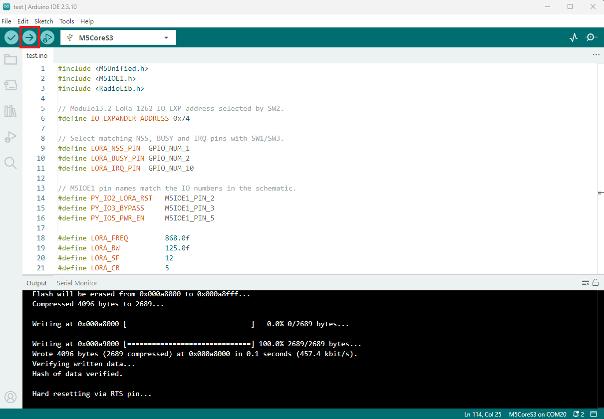
- 2. 选中设备端口,点击 Arduino IDE 左上角编译上传按钮,等待程序完成编译并上传至设备。
5. 信息收发效果展示
发送端会每秒发送一次包含计数的字符串,接收端会打印接收到的字符串,并显示 RSSI 等信息。

- 发送端串口返回信息:
[SX1262] Sending #34 packet ... Transmission finished!- 接收端串口返回信息:
[SX1262] Received packet:
[SX1262] Data:           Module13.2 LoRa-1262 #34
[SX1262] RSSI:           -0.00 dBm
[SX1262] SNR:            5.00 dB
[SX1262] Frequency error: 23.01 HzPage Tools