

Arduino 上手教程
2. 设备开发 & 案例程序
3. M5Unified
4. M5GFX
5. 扩展模块
Unit
Module
Atomic
Tab5
IoT
Module13.2 QRCode Arduino 使用教程
1. 准备工作
环境配置: 参考Arduino IDE上手教程完成 IDE 安装,并根据实际使用的开发板安装对应的板管理,与需要的驱动库。
使用到的驱动库:
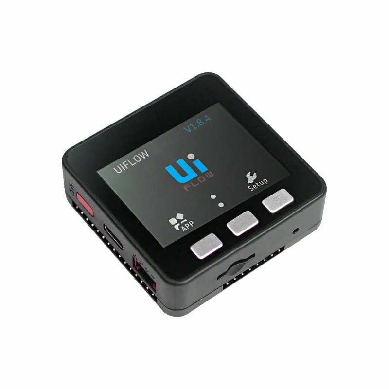
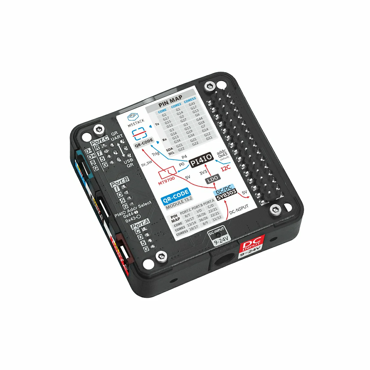
- 使用到的硬件产品:
2. 注意事项
3. 案例程序
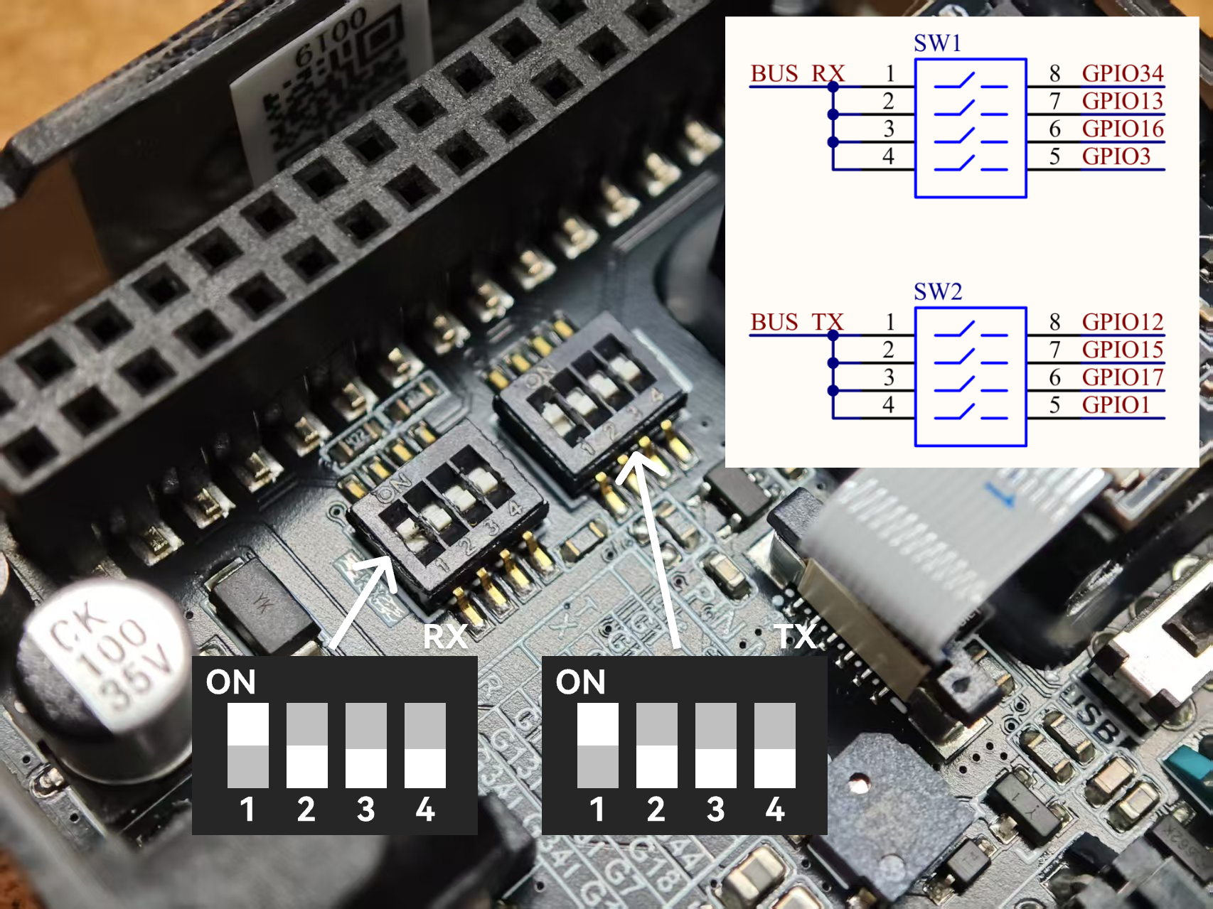
本教程中使用的主控设备为 Basic v2.7 ,搭配 Module13.2 QRCode 实现一维 / 二维码解析。 使用前请参考下图,将引脚拨码开关,切换到指定位置。
3.1 引脚拨码开关
本案例搭配主控设备 Basic v2.7 使用,并使用 G34 (RX) 和 G12 (TX) 作为通信引脚,具体引脚拨码开关配置如下图所示。
3.2 基础扫码程序
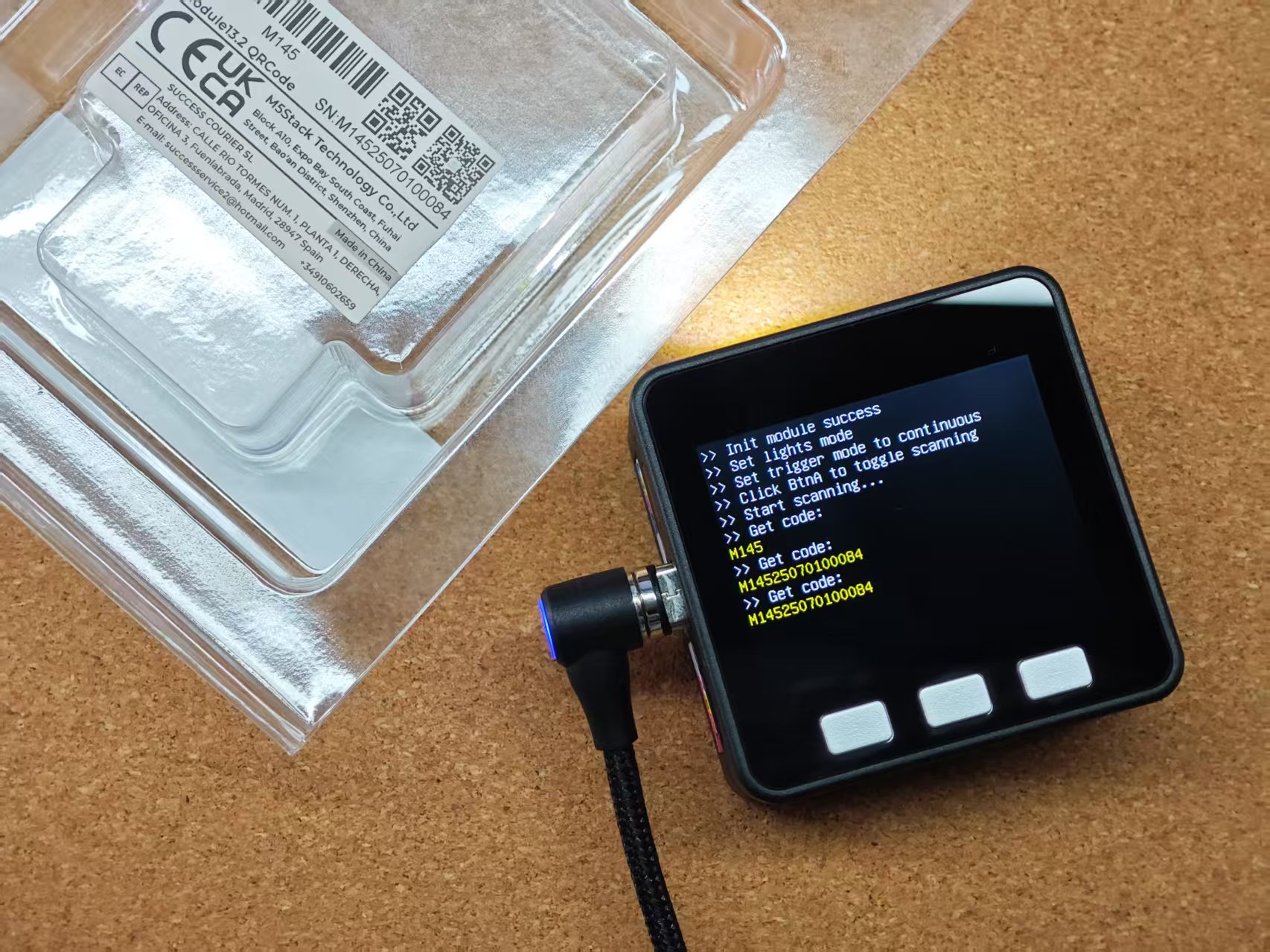
该案例程序将设置 Module13.2 QRCode 进入按键扫码模式。单击按键 A 将通过 UART 接口发送启动扫码和停止扫码指令。 保持按下按键 B 将通过模组 TRIG 引脚控制开始扫码,释放按键 B 则停止扫码。在扫码成功后,将显示解码结果至屏幕。
/*
 * SPDX-FileCopyrightText: 2025 M5Stack Technology CO LTD
 *
 * SPDX-License-Identifier: MIT
 */
#include <Arduino.h>
#include <M5Unified.h>
#include <M5ModuleQRCode.h>

M5ModuleQRCode module_qrcode;

void setup()
{
    M5.begin();
    M5.Display.setFont(&fonts::efontCN_16);
    M5.Display.setTextScroll(true);

    /* Set module config */
    auto cfg     = module_qrcode.getConfig();
    cfg.pin_tx   = 12;
    cfg.pin_rx   = 34;
    cfg.baudrate = 115200;
    cfg.serial   = &Serial1;
    module_qrcode.setConfig(cfg);

    /* Init module */
    while (!module_qrcode.begin()) {
        M5.Display.setTextColor(TFT_RED);
        M5.Display.println(">> Init module failed, retry...");
        delay(1000);
    }
    M5.Display.setTextColor(TFT_WHITE);
    M5.Display.println(">> Init module success");

    /* Set light mode */
    M5.Display.println(">> Set lights mode");
    module_qrcode.setFillLightMode(QRCodeM14::FILL_LIGHT_ON_DECODE);
    module_qrcode.setPosLightMode(QRCodeM14::POS_LIGHT_ON_DECODE);

    /* Set trigger mode */
    M5.Display.println(">> Set trigger mode to continuous");
    module_qrcode.setTriggerMode(QRCodeM14::TRIGGER_MODE_CONTINUOUS);
    module_qrcode.stopDecode();

    M5.Display.println(">> Click BtnA to toggle scanning");
}

void loop()
{
    M5.update();

    static bool is_scanning = false;

    /* If BtnA was clicked */
    if (M5.BtnA.wasClicked()) {
        is_scanning = !is_scanning;

        if (is_scanning) {
            module_qrcode.startDecode();
        } else {
            module_qrcode.stopDecode();
        }

        M5.Display.setTextColor(TFT_WHITE);
        M5.Display.println(is_scanning ? ">> Start scanning..." : ">> Stop scanning");
    }

    /* Update module */
    module_qrcode.update();

    /* If scan result available */
    if (module_qrcode.available()) {
        auto result = module_qrcode.getScanResult();

        /* Display result */
        M5.Display.setTextColor(TFT_WHITE);
        M5.Display.println(">> Get code:");
        M5.Display.setTextColor(TFT_YELLOW);
        M5.Display.println(result.c_str());
    }
}3.3 扫码触发控制
模组支持配置不同的扫码触发方式。
enum TriggerMode_t {
        TRIGGER_MODE_KEY = 0,
        TRIGGER_MODE_CONTINUOUS = 1,
        TRIGGER_MODE_AUTO = 2,
        TRIGGER_MODE_PULSE = 4,
        TRIGGER_MODE_MOTION_SENSING = 5
};TRIGGER_MODE_KEY:- 配置按键模式后,通过 TRIG 设置并保持低电平触发扫码解码,成功读取后解码即停止,再次触发需先恢复高电平,再次设置低电平触发。
TRIGGER_MODE_CONTINUOUS:- 配置连续模式后,通过 TRIG 触发下降沿进入连续模式,模块将保持扫码解码状态,直到再次触发 TRIG 下降沿后停止扫码解码。
TRIGGER_MODE_AUTO:- 配置自动模式后,模块将保持扫码解码状态,直到切换其他模式。 该模式下不支持通过 TRIG 或 UART 指令控制扫码解码
TRIGGER_MODE_PULSE:- 配置脉冲模式后,通过 TRIG 产生低电平持续 20ms 的脉冲用于触发单次扫码解码。
TRIGGER_MODE_MOTION_SENSING:- 配置运动感应模式后,模块将根据视觉场景的变化自动触发扫码解码,无法停止,直到切换其他模式。该模式下,也支持使用 TRIG 设置低电平触发扫码。
TRIGGER_MODE_AUTO模式以外,其他模式在运行过程中可通过 UART 指令控制扫码解码。2. 模式配置将写入设备,支持断电保存。
通过 setTriggerMode 函数配置触发模式:
module_qrcode.setTriggerMode(QRCodeM14::TRIGGER_MODE_KEY);
// module_qrcode.setTriggerMode(QRCodeM14::TRIGGER_MODE_CONTINUOUS);
// module_qrcode.setTriggerMode(QRCodeM14::TRIGGER_MODE_AUTO);
// module_qrcode.setTriggerMode(QRCodeM14::TRIGGER_MODE_PULSE);
// module_qrcode.setTriggerMode(QRCodeM14::TRIGGER_MODE_MOTION_SENSING);Module13.2 QRCode 支持通过两种方式控制执行扫码解码:
- 方法一:调用
startDecode()函数,该方式使用串口发送解码指令来触发扫码,即软件触发扫码。 - 方法二:调用
setTriggerLevel(false)函数 (通过控制 TRIG 引脚电平触发扫码,低电平有效)。
通过 startDecode 函数控制扫码:
module_qrcode.startDecode();
delay(1000);
module_qrcode.stopDecode();
delay(1000);通过 setTriggerLevel 函数控制扫码:
module_qrcode.setTriggerLevel(false);
delay(1000);
module_qrcode.setTriggerLevel(true);
delay(1000);3.4 补光灯工作模式
使用 setFillLightMode() 设置补光灯模式,枚举定义如下:
enum FillLightMode_t {
        FILL_LIGHT_OFF       = 0,  // Light off
        FILL_LIGHT_ON_DECODE = 2,  // Light on during decoding
        FILL_LIGHT_ON        = 3   // Light on
};FILL_LIGHT_OFF:- 补光灯常灭
FILL_LIGHT_ON_DECODE:- 补光灯解码时常亮
FILL_LIGHT_ON:- 补光灯常亮
通过 setFillLightMode 函数进行配置:
module_qrcode.setFillLightMode(QRCodeM14::FILL_LIGHT_ON_DECODE);
// module_qrcode.setFillLightMode(QRCodeM14::FILL_LIGHT_ON);
// module_qrcode.setFillLightMode(QRCodeM14::FILL_LIGHT_OFF);3.5 定位灯工作模式
使用 setPosLightMode() 设置补光灯模式,枚举定义如下:
enum PosLightMode_t {
        POS_LIGHT_OFF             = 0,  // Light off
        POS_LIGHT_FLASH_ON_DECODE = 1,  // Light flashing during decoding
        POS_LIGHT_ON_DECODE       = 2   // Light on during decoding
};module_qrcode.setPosLightMode(QRCodeM14::POS_LIGHT_ON_DECODE);
// module_qrcode.setPosLightMode(QRCodeM14::POS_LIGHT_FLASH_ON_DECODE);
// module_qrcode.setPosLightMode(QRCodeM14::POS_LIGHT_OFF);POS_LIGHT_OFF:- 定位灯常灭
POS_LIGHT_FLASH_ON_DECODE:- 定位灯解码时闪烁
POS_LIGHT_ON_DECODE:- 定位灯解码时常亮
4. USB 模式
Module13.2 QRCode 支持配置多种 USB 工作模式,支持 USB-CDC 串口,USB HID 键盘,USB-HID POS 设备功能。
4.1 USB/UART 接口切换
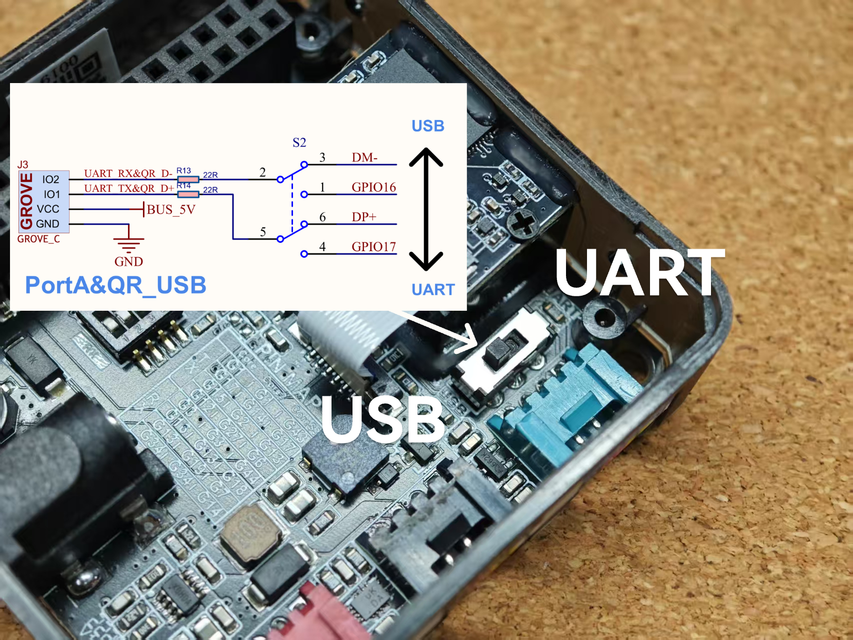
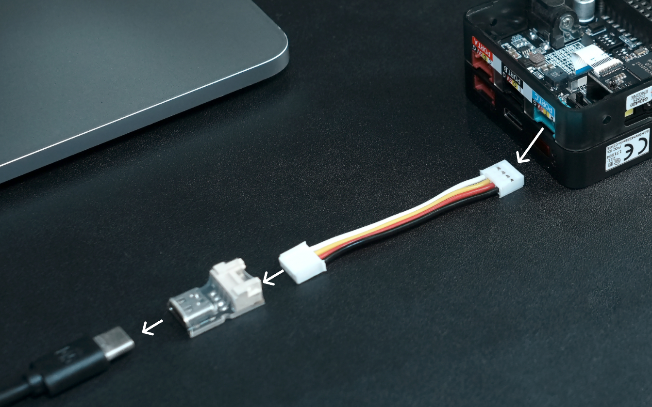
使用前需将板载的接口切换开关切换至 USB 侧,该操作用于切换内置模组的 USB 引脚 (USB_D+,USB_D-) 连接至 PORT.C 接口。然后使用 Grove to USBC 转接板将 PORT.C 端口连接至 PC。 并参考下方案例程序,根据需求配置不同的 USB 工作模式。
4.2 USB-CDC
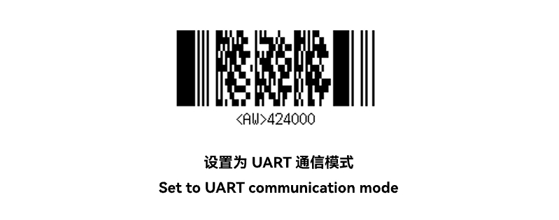
参考以下案例调用 setModeUsbSerial() 函数,设置进入 USB-CDC 模式。设备连接 PC 后将启用虚拟串口,用户可使用串口调试助手或终端工具连接对应端口,长按按键 A 进行扫码,扫码成功后在调试窗口即可获取扫码结果。该模式下,同时可通过串口发送控制指令。如果重新切换至 UART 模式,可发送 HEX 数值:21 42 40 00 (配置串行通信指令),QR 模组接收到指令后会短暂闪烁一下,说明配置 UART 接口成功,此时 USB-CDC 接口将关闭。
#include <Arduino.h>
#include <M5Unified.h>
#include <M5ModuleQRCode.h>

M5ModuleQRCode module_qrcode;

void setup()
{
    M5.begin();
    /* Set module config */
    auto cfg     = module_qrcode.getConfig();
    cfg.pin_tx   = 12;
    cfg.pin_rx   = 34;
    cfg.baudrate = 115200;
    cfg.serial   = &Serial1;
    module_qrcode.setConfig(cfg);

    /* Init module */
    while (!module_qrcode.begin()) {
        delay(1000);
    }
    module_qrcode.setFillLightMode(QRCodeM14::FILL_LIGHT_ON_DECODE);
    module_qrcode.setPosLightMode(QRCodeM14::POS_LIGHT_ON_DECODE);
    module_qrcode.setTriggerMode(QRCodeM14::TRIGGER_MODE_KEY);
    module_qrcode.stopDecode();
    module_qrcode.setModeUsbSerial();
    M5.Display.setFont(&fonts::FreeMonoBoldOblique24pt7b);
    M5.Display.println("Hold BtnA");
    M5.Display.println("Start Scan");
}

void loop()
{
    M5.update();
    if (M5.BtnA.isPressed()) {
        module_qrcode.setTriggerLevel(false);
    } else {
        module_qrcode.setTriggerLevel(true);
    }
}4.3 USB-HID
调用 setModeUsbKeyboard() 函数,设置进入 USB-HID 模式。设备将模拟 USB Keyboard 设备,长按按键 A 进行扫码,扫码成功后将以键盘输出形式,直接输入扫码结果字符。
4.4 USB-HID POS
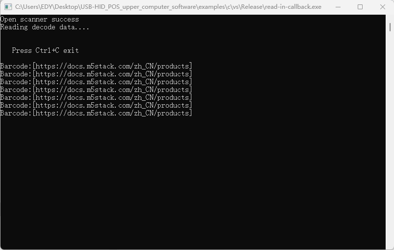
调用 setModeUsbPos() 函数,设置进入 USB-HID POS 模式。设备将模拟标准扫码 POS 设备,该模式需配合标准协议上位机使用。当前上位机仅提供 Windows 版本,其他平台可以参考上位机源码进行移植。
请运行上位机软件包中的examples\c\vs\Release\read-in-callback.exe可执行文件,扫描测试二维码,扫码结果将显示在上位机窗口中。
4.5 USB HID-POS 驱动报错解决方法
若在使用 USB HID-POS 时,设备管理器中显示如下驱动报错:
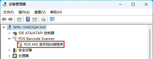
请按以下步骤操作:
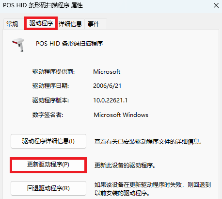
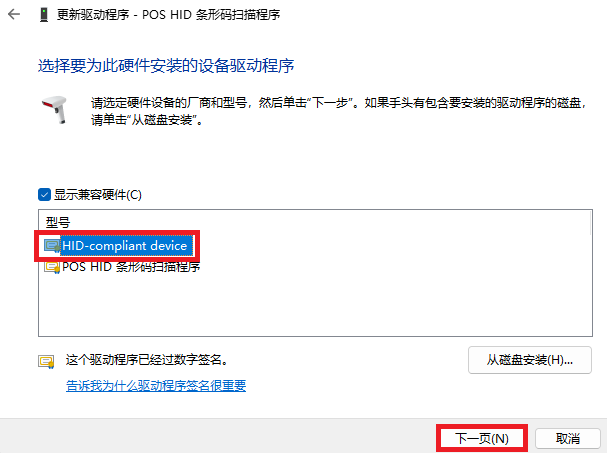
1. 双击上方报错驱动,选择驱动程序选项卡,点击更新驱动程序按钮,选择浏览我的电脑以查找驱动程序;
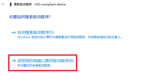
2. 继续选择让我从计算机上的设备驱动程序列表中选取,在型号列表中选择HID-compliant device,然后点击下一页按钮,出现下方最后一个页面时说明驱动更新成功。
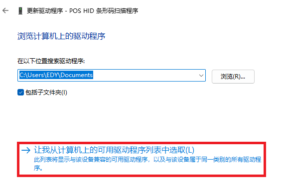
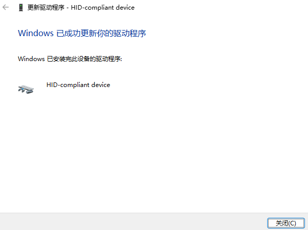
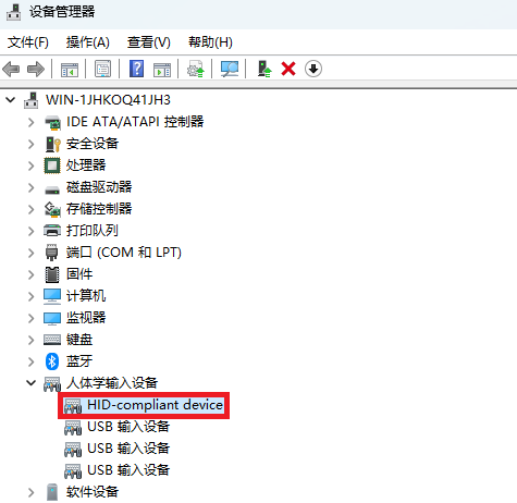
完成上述步骤后,设备管理器中出现下图所示HID-compliant device设备时,使用 USB HID-POS 时就可以正常工作了。
5. 上位机配置工具
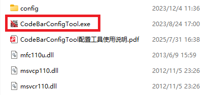
下载,并打开 中的 CodeBarConfigTool.exe ,工具如下图所示。
下方以 USB-CDC 模式修改为串口模式为例,介绍如何使用配置工具:
首先,点击下图中的①处图标,然后在②处选中对应的 USB 接口,点击③处的连接按钮,连接成功后④处显示为联机状态。

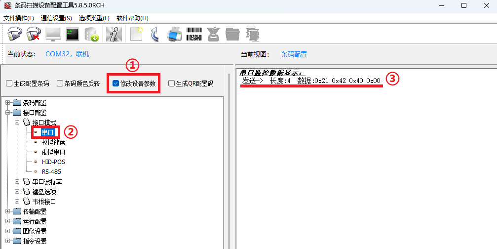
然后,勾选上下图中的①处,找到②处并双击,当出现③处的配置信息后,说明配置串口成功。
配置工具使用说明请参考软件包中的 CodeBarConfigTool.pdf 文档。