

Arduino 上手教程
2. 设备开发 & 案例程序
3. M5Unified
4. M5GFX
5. 扩展模块
Unit
Module
Atomic
Tab5
IoT
Unit 2Relay Arduino 使用教程
1. 准备工作
- 环境配置:参考 Arduino IDE 上手教程 完成 IDE 安装,并根据实际使用的开发板安装对应的板管理与驱动库。
- 使用到的驱动库:
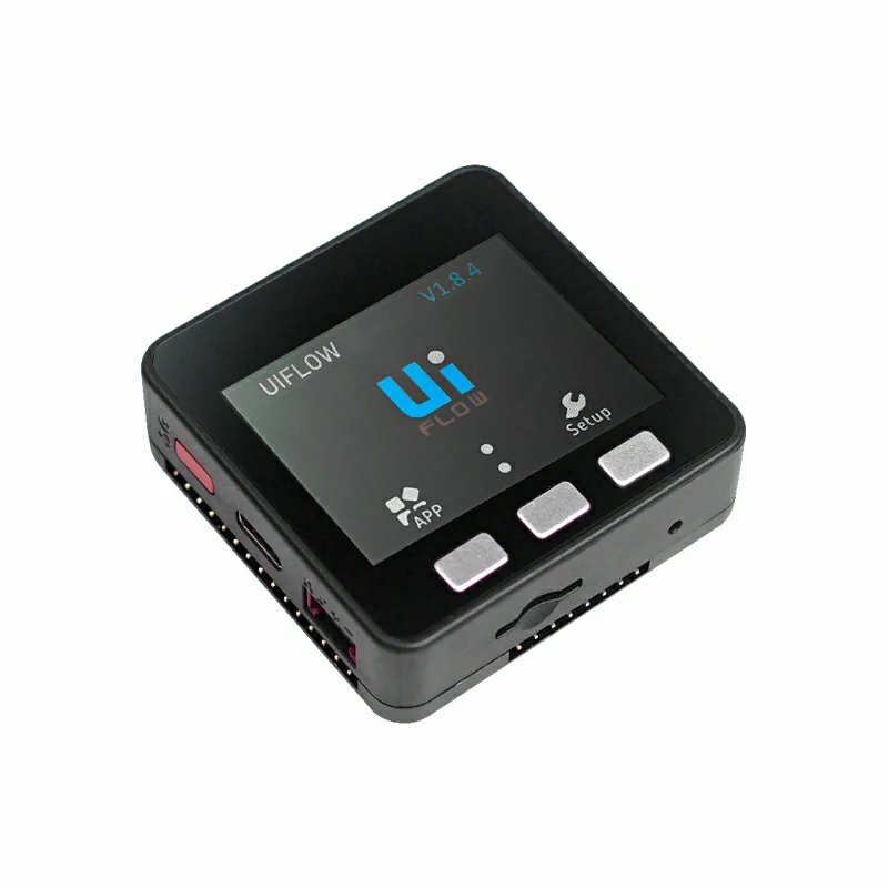
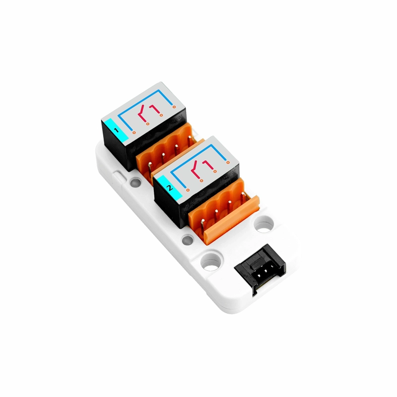
- 使用到的硬件产品:
2. 注意事项
引脚兼容性
由于每款主机的引脚配置不同,为了让用户更方便地使用,M5Stack 官方提供了引脚兼容性表,方便用户查看,请根据实际引脚连接情况修改案例程序。
3. 案例程序
- 本教程使用 Basic V2.7 搭配 Unit 2Relay,并将模块连接到 Port A。Unit 2Relay 通过 GPIO 高低电平直接控制, RELAY-1 对应 Basic V2.7 的
G22,RELAY-2 对应 Basic V2.7 的G21。输出高电平时对应继电器吸合且状态指示灯点亮,输出低电平时继电器释放。
cpp
1 2 3 4 5 6 7 8 9 10 11 12 13 14 15 16 17 18 19 20 21 22 23 24 25 26 27 28 29 30 31 32 33 34 35 36 37 38 39 40 41 42 43 44 45 46 47 48 49 50 51 52 53 54 55 56 57 58 59 60 61 62 63 64 65 66 67 68 69 70 71 72 73 74 75 76 77 78 79 80 81 82 83 84 85 86 87 88 89 90 91 92 93 94 95 96 97 98 99 100 101 102 103 104 105 106 107 108 109 110 111 112 113 114 115 116 117 118 119 120 121 122 123 124 125 126 127 128 129 130 131 132 133 134 135 136 137 138 139 140 141 142 143 144 145 146 147 148 149 150 151 152 153 154 155 156 157 158 159 160 161 162 163 164 165 166 167 168 169 170 171 172
#include <M5Unified.h>

namespace {
constexpr uint16_t COLOR_BG      = 0x1082;
constexpr uint16_t COLOR_SURFACE = 0x2104;
constexpr uint16_t COLOR_HEADER  = 0x0349;
constexpr uint16_t COLOR_BORDER  = 0x52AA;
constexpr uint16_t COLOR_MUTED   = 0xBDF7;
constexpr uint16_t COLOR_GREEN   = 0x2E8B;
constexpr uint16_t COLOR_RED     = 0xD249;

constexpr int16_t CHANNEL_Y       = 148;
constexpr int16_t CHANNEL_WIDTH   = 100;
constexpr int16_t CHANNEL_HEIGHT  = 43;
constexpr int16_t CHANNEL_GAP     = 20;
constexpr int16_t CHANNEL_START_X = 50;

int relayPins[2]   = {-1, -1};
bool relayState[2] = {false, false};
uint8_t stepIndex  = 0;

void drawControlStatus()
{
    M5.Display.fillRect(0, 38, 320, 36, COLOR_BG);
    M5.Display.setFont(&fonts::Font2);
    M5.Display.setTextDatum(textdatum_t::middle_left);
    M5.Display.setTextColor(COLOR_MUTED, COLOR_BG);
    M5.Display.drawString("CONTROL", 12, 56);
    M5.Display.drawString("CHANNELS", 174, 56);

    M5.Display.fillRoundRect(82, 44, 70, 25, 4, COLOR_GREEN);
    M5.Display.fillRoundRect(258, 44, 50, 25, 4, COLOR_SURFACE);
    M5.Display.drawRoundRect(258, 44, 50, 25, 4, COLOR_BORDER);

    M5.Display.setTextDatum(textdatum_t::middle_center);
    M5.Display.setTextColor(TFT_BLACK, COLOR_GREEN);
    M5.Display.drawString("GPIO", 117, 56);
    M5.Display.setTextColor(TFT_WHITE, COLOR_SURFACE);
    M5.Display.drawString("2", 283, 56);
}

void drawAction(const char *message)
{
    M5.Display.fillRoundRect(10, 81, 300, 38, 4, COLOR_SURFACE);
    M5.Display.drawRoundRect(10, 81, 300, 38, 4, COLOR_BORDER);
    M5.Display.setFont(&fonts::Font2);
    M5.Display.setTextDatum(textdatum_t::middle_left);
    M5.Display.setTextColor(COLOR_MUTED, COLOR_SURFACE);
    M5.Display.drawString("LAST ACTION", 20, 100);
    M5.Display.setTextColor(TFT_WHITE, COLOR_SURFACE);
    M5.Display.drawString(message, 119, 100);
}

void drawChannel(uint8_t channel)
{
    const bool isOn      = relayState[channel];
    const uint16_t color = isOn ? COLOR_GREEN : COLOR_BORDER;
    const int16_t x = CHANNEL_START_X + channel * (CHANNEL_WIDTH + CHANNEL_GAP);
    char channelLabel[5] = {};
    snprintf(channelLabel, sizeof(channelLabel), "CH%u",
             static_cast<unsigned>(channel + 1));

    M5.Display.fillRoundRect(x, CHANNEL_Y, CHANNEL_WIDTH, CHANNEL_HEIGHT, 4,
                             COLOR_SURFACE);
    M5.Display.drawRoundRect(x, CHANNEL_Y, CHANNEL_WIDTH, CHANNEL_HEIGHT, 4,
                             color);
    M5.Display.setTextDatum(textdatum_t::middle_center);
    M5.Display.setFont(&fonts::Font2);
    M5.Display.setTextColor(COLOR_MUTED, COLOR_SURFACE);
    M5.Display.drawString(channelLabel, x + CHANNEL_WIDTH / 2, CHANNEL_Y + 12);
    M5.Display.setTextColor(isOn ? COLOR_GREEN : TFT_WHITE, COLOR_SURFACE);
    M5.Display.drawString(isOn ? "ON" : "OFF", x + CHANNEL_WIDTH / 2,
                          CHANNEL_Y + 31);
}

void drawAllChannels()
{
    M5.Display.fillRect(0, 125, 320, 22, COLOR_BG);
    M5.Display.setFont(&fonts::Font2);
    M5.Display.setTextDatum(textdatum_t::middle_left);
    M5.Display.setTextColor(COLOR_MUTED, COLOR_BG);
    M5.Display.drawString("RELAY STATUS", 10, 136);

    for (uint8_t channel = 0; channel < 2; ++channel) {
        drawChannel(channel);
    }
}

void drawButtonHint(int16_t x, char button, const char *label, uint16_t color)
{
    char buttonLabel[2] = {button, '\0'};

    M5.Display.fillCircle(x, 220, 11, color);
    M5.Display.setFont(&fonts::Font2);
    M5.Display.setTextDatum(textdatum_t::middle_center);
    M5.Display.setTextColor(TFT_BLACK, color);
    M5.Display.drawString(buttonLabel, x, 220);
    M5.Display.setTextDatum(textdatum_t::middle_left);
    M5.Display.setTextColor(TFT_WHITE, COLOR_SURFACE);
    M5.Display.drawString(label, x + 16, 220);
}

void drawMainUi()
{
    M5.Display.fillScreen(COLOR_BG);
    M5.Display.fillRect(0, 0, 320, 34, COLOR_HEADER);
    M5.Display.setFont(&fonts::Font4);
    M5.Display.setTextDatum(textdatum_t::middle_center);
    M5.Display.setTextColor(TFT_WHITE, COLOR_HEADER);
    M5.Display.drawString("UNIT 2RELAY", 160, 17);

    drawControlStatus();
    drawAction("Ready");
    drawAllChannels();

    M5.Display.fillRect(0, 202, 320, 38, COLOR_SURFACE);
    M5.Display.drawFastHLine(0, 202, 320, COLOR_BORDER);
    drawButtonHint(48, 'A', "STEP", COLOR_GREEN);
    drawButtonHint(210, 'C', "ALL", COLOR_RED);
}

void writeRelay(uint8_t channel, bool state)
{
    digitalWrite(relayPins[channel], state ? HIGH : LOW);
    relayState[channel] = state;
}
}  // namespace

void setup()
{
    M5.begin();
    Serial.begin(115200);
    M5.Display.setRotation(1);

    // Grove Port A: white wire controls RELAY-1, yellow wire controls RELAY-2.
    relayPins[0] = M5.getPin(m5::pin_name_t::port_a_pin2);
    relayPins[1] = M5.getPin(m5::pin_name_t::port_a_pin1);
    for (uint8_t channel = 0; channel < 2; ++channel) {
        pinMode(relayPins[channel], OUTPUT);
        writeRelay(channel, false);
    }

    drawMainUi();
}

void loop()
{
    M5.update();

    if (M5.BtnA.wasPressed()) {
        const uint8_t channel = stepIndex % 2;
        const bool state      = stepIndex < 2;
        char message[20]      = {};

        writeRelay(channel, state);
        snprintf(message, sizeof(message), "Relay %u  %s",
                 static_cast<unsigned>(channel + 1), state ? "ON" : "OFF");
        drawAction(message);
        drawChannel(channel);
        stepIndex = (stepIndex + 1) % 4;
    }

    if (M5.BtnC.wasPressed()) {
        const bool state = !(relayState[0] && relayState[1]);
        for (uint8_t channel = 0; channel < 2; ++channel) {
            writeRelay(channel, state);
        }

        drawAction(state ? "All channels ON" : "All channels OFF");
        drawAllChannels();
    }
}4. 编译上传
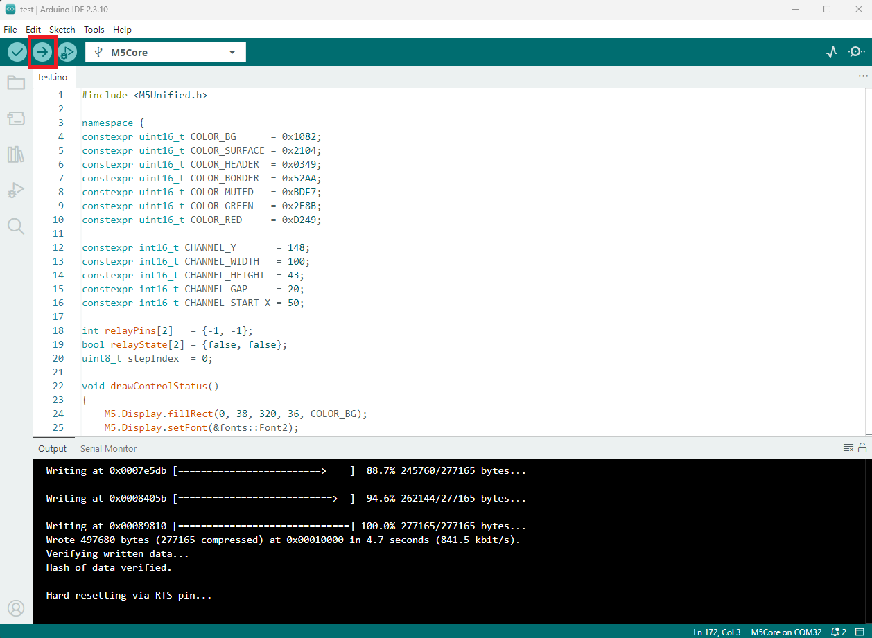
- 复制粘贴上述例程代码到项目代码区,选中设备端口(详情请参考 程序编译与烧录),点击 Arduino IDE 左上角编译上传按钮,等待程序完成编译并上传至设备。
5. 继电器控制
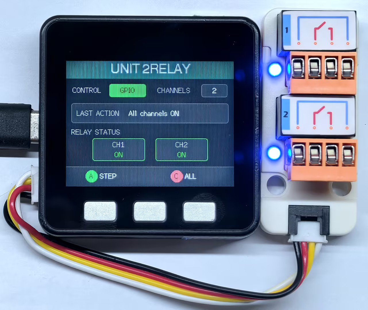
- 按下按键 A,两路继电器将按照
CH1 ON → CH2 ON → CH1 OFF → CH2 OFF的顺序循环切换;按下按键 C:如果当前并非两路全部接通,则接通全部继电器;如果两路已经全部接通,则断开全部继电器。屏幕中的CH1、CH2状态块和LAST ACTION区域会同步显示当前控制结果。
Page Tools