

Arduino 上手教程
2. 设备开发 & 案例程序
3. M5Unified
4. M5GFX
5. 扩展模块
Unit
Module
Atomic
Tab5
IoT
Unit Color Arduino 使用教程
1. 准备工作
- 环境配置:参考 Arduino IDE 上手教程 完成 IDE 安装,并根据实际使用的开发板安装对应的板管理器和所需驱动库。
- 使用到的驱动库:
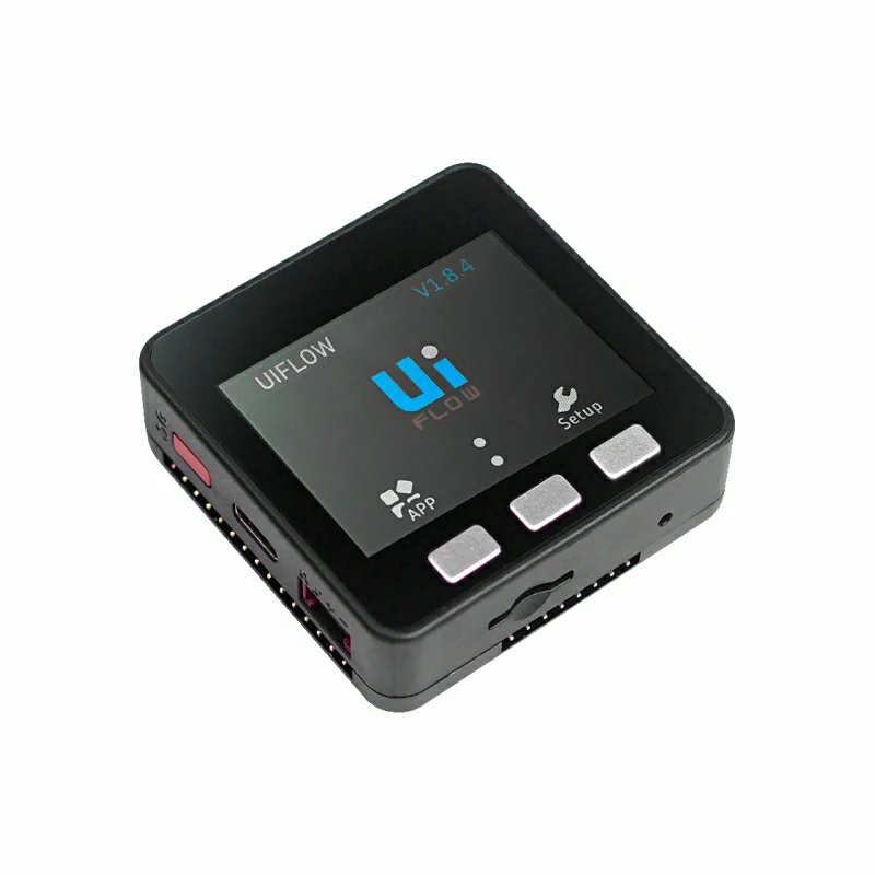
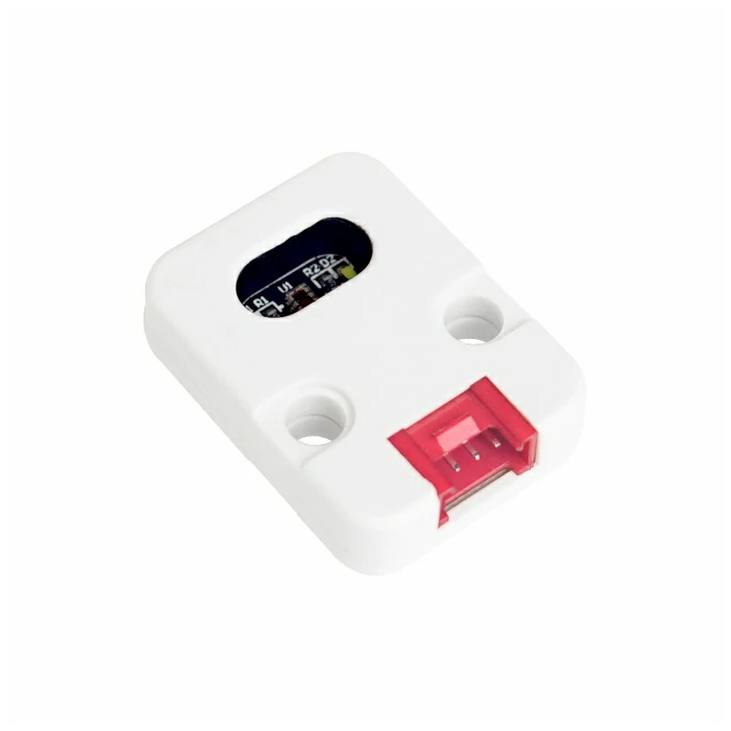
- 使用到的硬件产品:
2. 注意事项
引脚兼容性
由于每款主机的引脚配置不同,为了让用户更方便地使用,M5Stack 官方提供了引脚兼容性表,方便用户查看,请根据实际引脚连接情况修改案例程序。
3. 案例程序
- 本教程中使用的主控设备为 Basic V2.7,搭配 Unit Color。Unit Color 采用 I2C 通信,默认地址为
0x29。设备连接后对应的引脚为G21 (SDA)、G22 (SCL)。
cpp
1 2 3 4 5 6 7 8 9 10 11 12 13 14 15 16 17 18 19 20 21 22 23 24 25 26 27 28 29 30 31 32 33 34 35 36 37 38 39 40 41 42 43 44 45 46 47 48 49 50 51 52 53 54 55 56 57 58 59 60 61 62 63 64 65 66 67 68 69 70 71 72 73
#include <M5Unified.h>
#include <M5GFX.h>
#include "Adafruit_TCS34725.h"

#define commonAnode  true  // set to false if using a common cathode LED.

byte gammatable[256];  // our RGB -> eye-recognized gamma color

static uint16_t color16(uint16_t r, uint16_t g, uint16_t b)
{
    uint16_t _color;
    _color = (uint16_t)(r & 0xF8) << 8;
    _color |= (uint16_t)(g & 0xFC) << 3;
    _color |= (uint16_t)(b & 0xF8) >> 3;
    return _color;
}

Adafruit_TCS34725 tcs = Adafruit_TCS34725(TCS34725_INTEGRATIONTIME_50MS, TCS34725_GAIN_4X);

void setup()
{
    M5.begin();
    M5.Power.begin();
    M5.Lcd.setTextSize(2);
    Serial.println("Color View Test!");
    while (!tcs.begin(TCS34725_ADDRESS, &Wire)) { //PORT.A
        Serial.println("No TCS34725 found ... check your connections");
        M5.Lcd.drawString("No Found sensor.", 50, 100, 4);
        delay(1000);
    }
    tcs.setIntegrationTime(TCS34725_INTEGRATIONTIME_154MS);  // Sets the integration time for the
    tcs.setGain(TCS34725_GAIN_4X);                           // Adjusts the gain on the TCS34725
}

void loop()
{
    uint16_t clear, red, green, blue;
    tcs.getRawData(&red, &green, &blue,
                   &clear);  // Reads the raw red, green, blue and clear channel
                             // values

    // Figure out some basic hex code for visualization.  生成对应的十六进制代码
    uint32_t sum = clear;
    float r, g, b;
    r = red;
    r /= sum;
    g = green;
    g /= sum;
    b = blue;
    b /= sum;
    r *= 256;
    g *= 256;
    b *= 256;
    uint16_t _color = color16((int)r, (int)g, (int)b);

    M5.Lcd.setCursor(0, 20);                 // Place the cursor at (0,20)
    M5.Lcd.fillRect(0, 20, 120, 80, BLACK);  // Fill the screen with a black rectangle

    M5.Lcd.print("C:");
    M5.Lcd.println(clear);
    M5.Lcd.print("R:");
    M5.Lcd.println(red);
    M5.Lcd.print("G:");
    M5.Lcd.println(green);
    M5.Lcd.print("B:");
    M5.Lcd.println(blue);
    M5.Lcd.print("0x");
    M5.Lcd.print((int)r, HEX);
    M5.Lcd.print((int)g, HEX);
    M5.Lcd.print((int)b, HEX);

    delay(1000);
}4. 编译上传
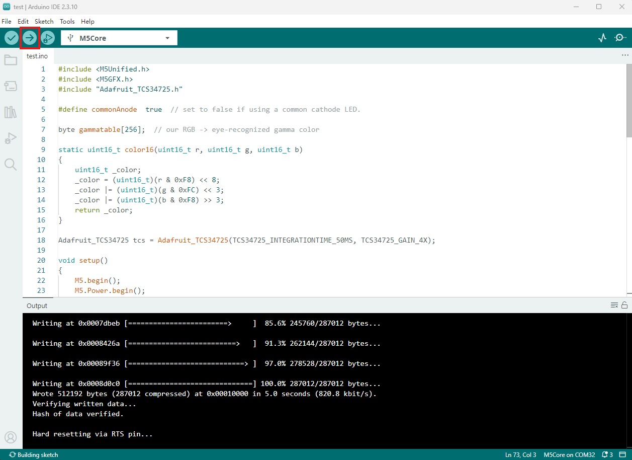
- 复制粘贴上述例程代码到项目代码区,选中设备端口(详情请参考 程序编译与烧录),点击 Arduino IDE 左上角编译上传按钮,等待程序完成编译并上传至设备。
5. 颜色识别
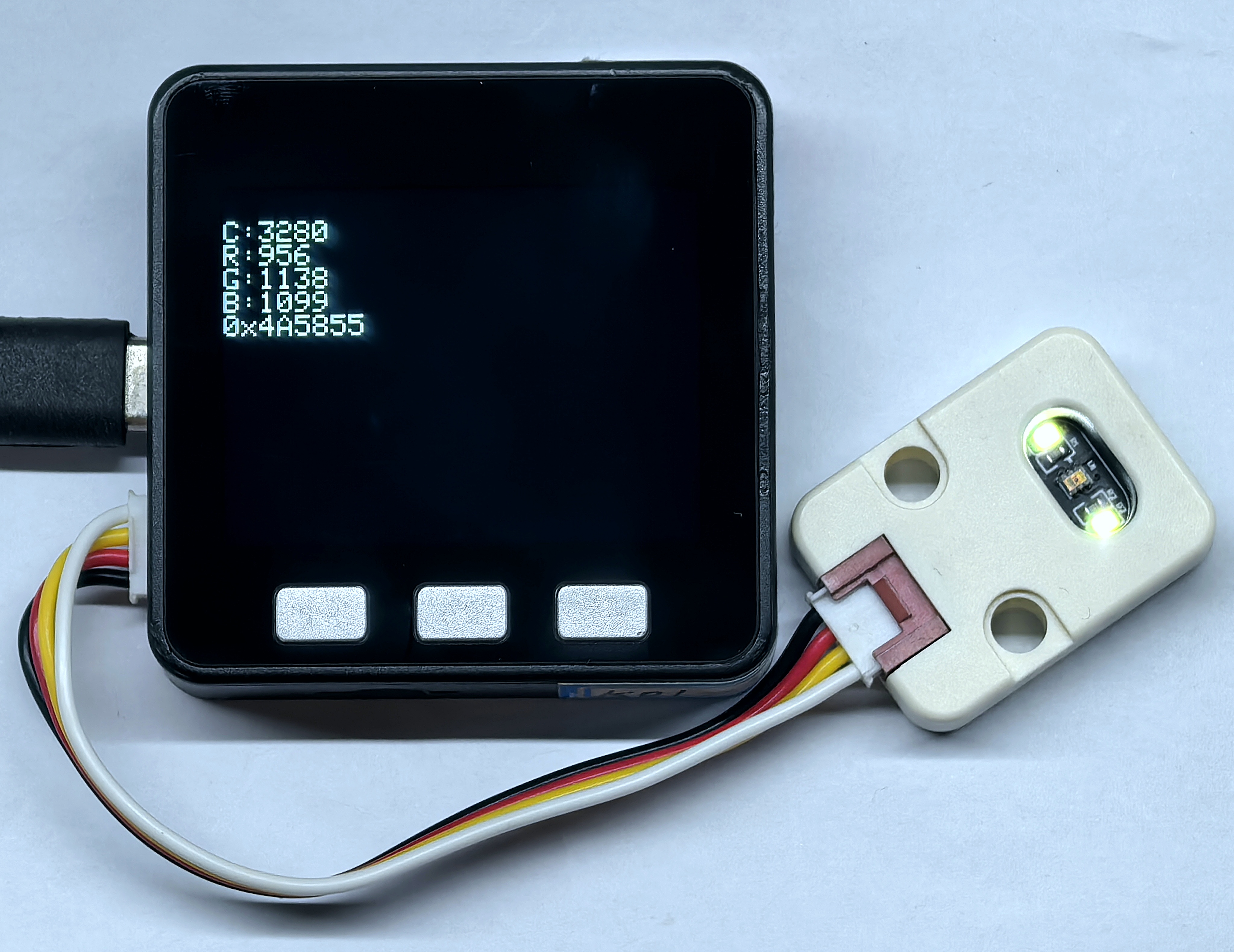
- 程序运行后,屏幕将每秒刷新一次 Unit Color 采集到的透明通道及红、绿、蓝通道原始值,并显示换算后的 RGB 十六进制数据。
Page Tools