

Arduino Quick Start
2. Devices & Examples
Demo Board-SHT30
3. M5Unified
4. M5GFX
5. Extensions
Unit
Module
Atomic
Tab5
IoT
Accessories
ADC Analog-to-Digital Conversion Module
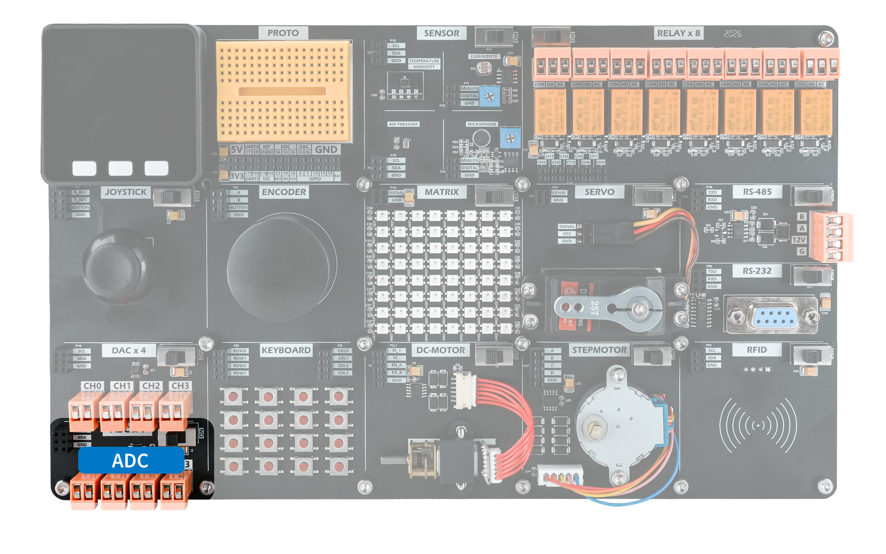
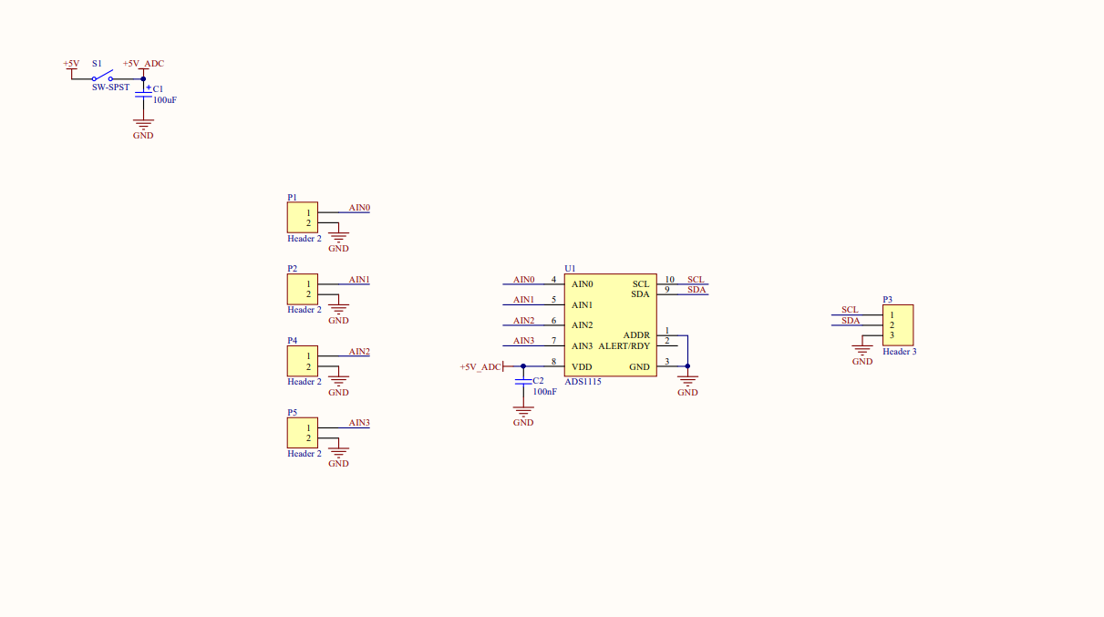
The demo board provides four ADC input channels that convert analog voltage signals into digital values for further analysis and calculation. The ADC module communicates over the I2C bus using the 7-bit device address 0x48.
Hardware Connection
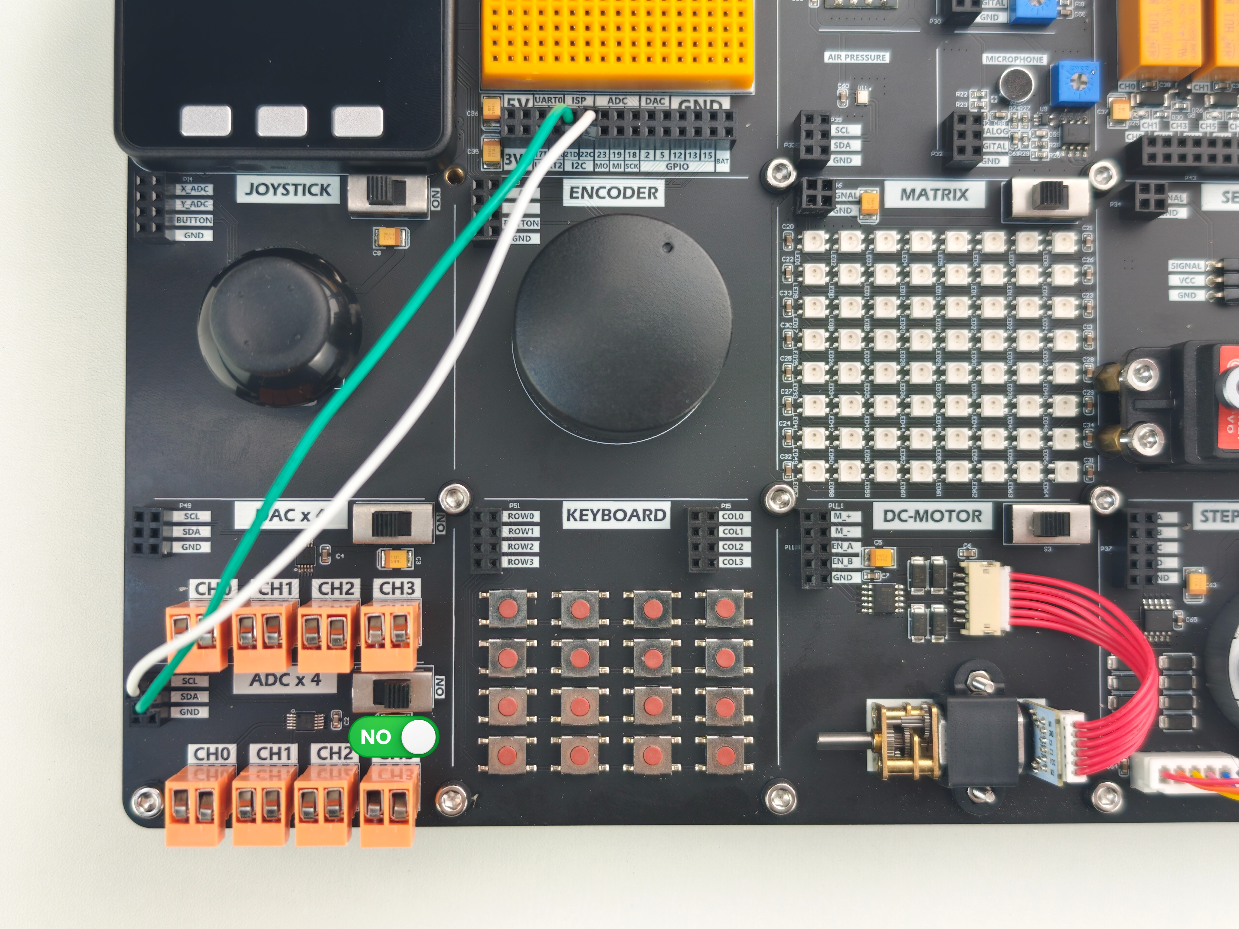
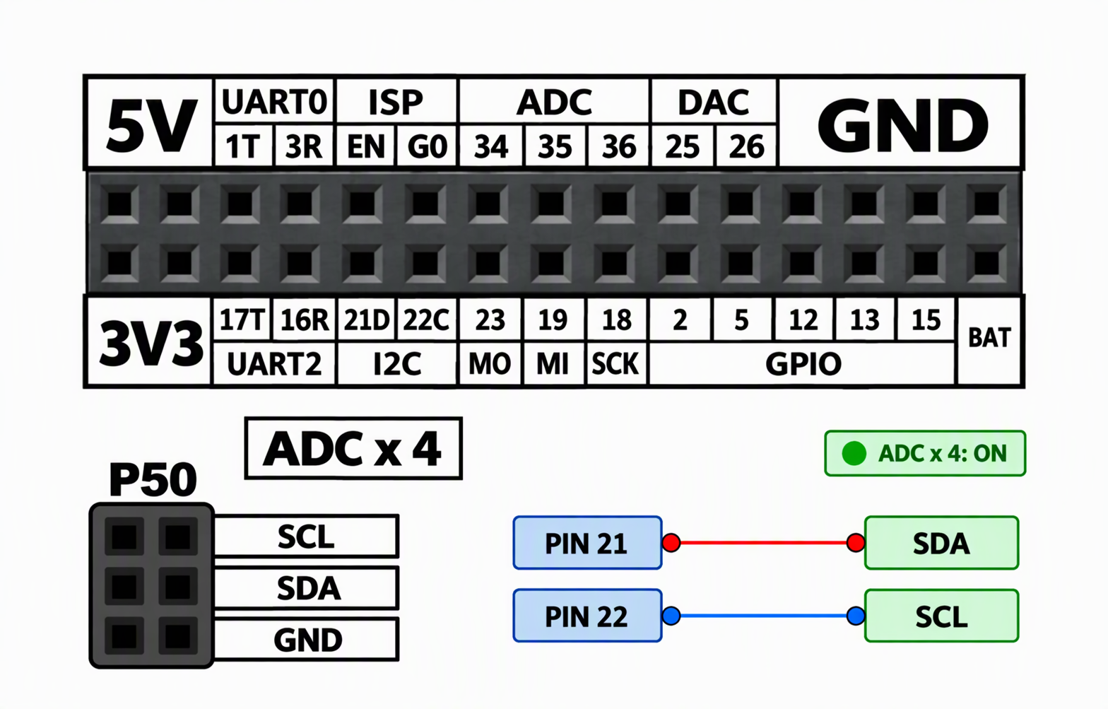
For I2C sensor devices, connect the module to the M5Core default I2C pins: PIN21 (SDA) and PIN22 (SCL).
Example Program
The program reads the four analog input channels in sequence and displays the raw ADC conversion values on the screen.
cpp
1 2 3 4 5 6 7 8 9 10 11 12 13 14 15 16 17 18 19 20 21 22 23 24 25 26 27 28 29 30 31 32 33 34 35 36 37 38 39 40 41 42 43 44 45 46 47 48 49 50 51 52 53 54 55 56 57 58 59 60 61 62 63 64 65 66 67 68 69 70 71 72 73 74 75 76 77 78 79 80 81 82 83
#include <M5Unified.h>

constexpr uint8_t ADC_ADDR = 0x48;

bool readADC(uint8_t ch, int16_t& value) {
  if (ch >= 4) {
    return false;
  }
  // Configuration of ADS1115:
  // OS = 1: Start a single conversion
  // MUX = 100 - 111: AIN0 - AIN3 relative to GND
  // PGA = 000: Gain 2/3, full scale ±6.144 V
  // MODE = 1: Single conversion mode
  // DR = 100: 128 SPS
  // COMP_QUE = 11: Disable comparator
  const uint8_t cfg[2] = {
    uint8_t(0xC1 | (ch << 4)),
    0x83
  };

  if (!M5.In_I2C.writeRegister(
          ADC_ADDR, 0x01, cfg, 2, 100000)) {
    return false;
  }
  // At 128 SPS, the typical conversion time is approximately 7.8 ms
  delay(10);

  uint8_t data[2];
  if (!M5.In_I2C.readRegister(
          ADC_ADDR, 0x00, data, 2, 100000)) {
    return false;
  }

  const uint16_t raw =
      (uint16_t(data[0]) << 8) | uint16_t(data[1]);

  const int32_t signedRaw =
      (raw & 0x8000u) ? int32_t(raw) - 65536 : int32_t(raw);

  value = static_cast<int16_t>(signedRaw);
  return true;
}

void setup() {
  M5.begin(M5.config());
  Serial.begin(115200);

  M5.Display.fillScreen(TFT_BLACK);
  M5.Display.setTextSize(2);
  M5.Display.setTextColor(TFT_WHITE, TFT_BLACK);
  M5.Display.drawString("ADC", 150, 10);
}

void loop() {
  M5.update();

  int16_t values[4] = {};
  bool readOK[4] = {};

  for (uint8_t i = 0; i < 4; ++i) {
    readOK[i] = readADC(i, values[i]);
  }

  for (uint8_t i = 0; i < 4; ++i) {
    const int x = 10 + (i % 2) * 150;
    const int y = 90 + (i / 2) * 30;

    M5.Display.fillRect(x, y, 150, 24, TFT_BLACK);
    M5.Display.setCursor(x, y);

    if (readOK[i]) {
      M5.Display.setTextColor(TFT_WHITE, TFT_BLACK);
      M5.Display.printf("CH%d:%6d", int(i), int(values[i]));
      Serial.printf("CH%d: %d\n", int(i), int(values[i]));
    } else {
      M5.Display.setTextColor(TFT_RED, TFT_BLACK);
      M5.Display.printf("CH%d: ERR", int(i));
      Serial.printf("CH%d: read failed\n", int(i));
    }
  }

  delay(500);
}After uploading the program, you should see the following result.
Page Tools