

Arduino Quick Start
2. Devices & Examples
Demo Board-SHT30
3. M5Unified
4. M5GFX
5. Extensions
Unit
Module
Atomic
Tab5
IoT
Accessories
RS-485 Module
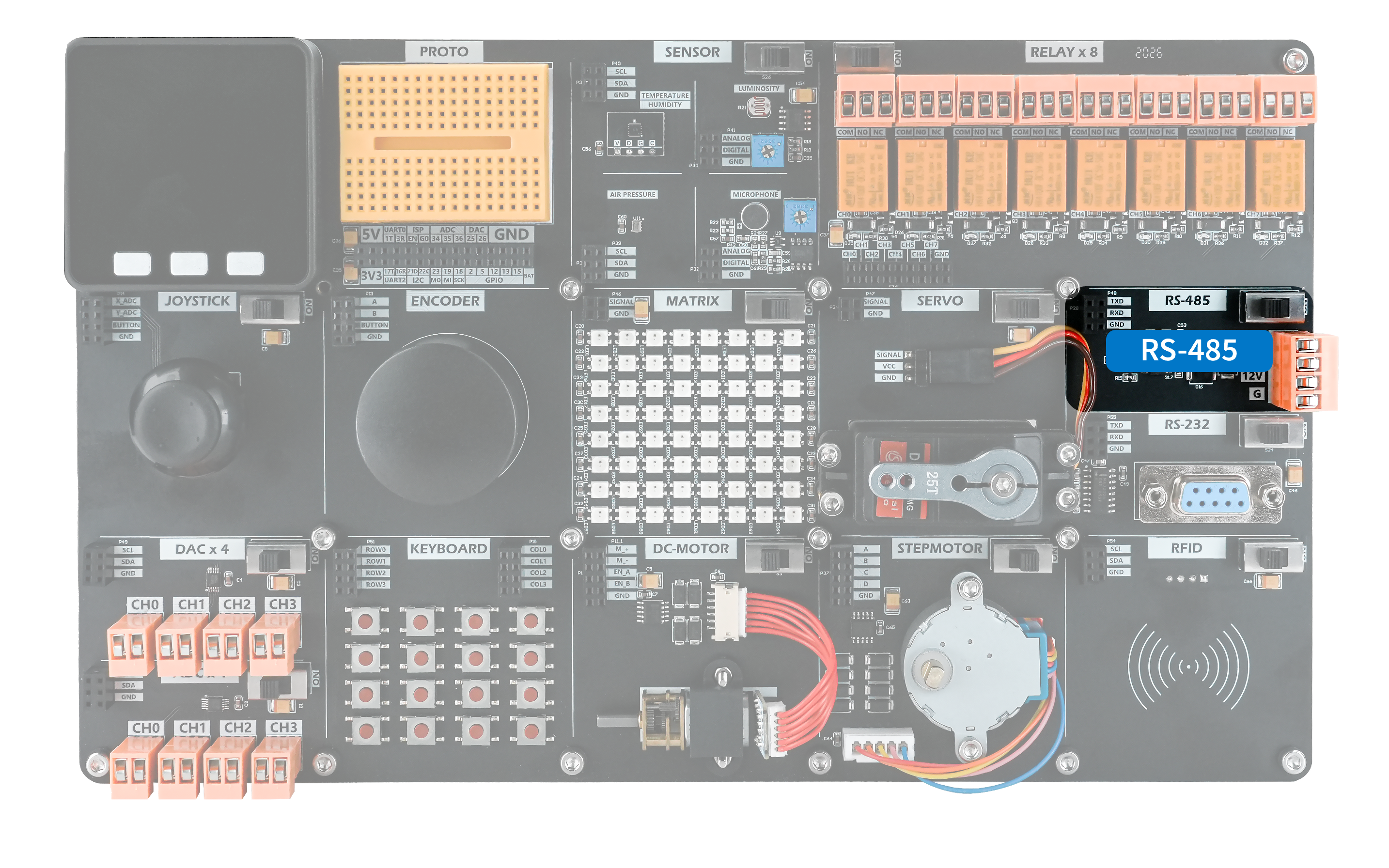
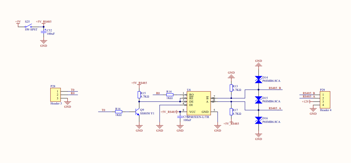
RS-485 is a widely used electrical standard in industrial control. Its differential signaling provides strong immunity to electronic noise. The RS-485 converter module on the demo board converts standard TTL-level signals to RS-485 levels, enabling protocol conversion and control of compatible devices.
Hardware Connection
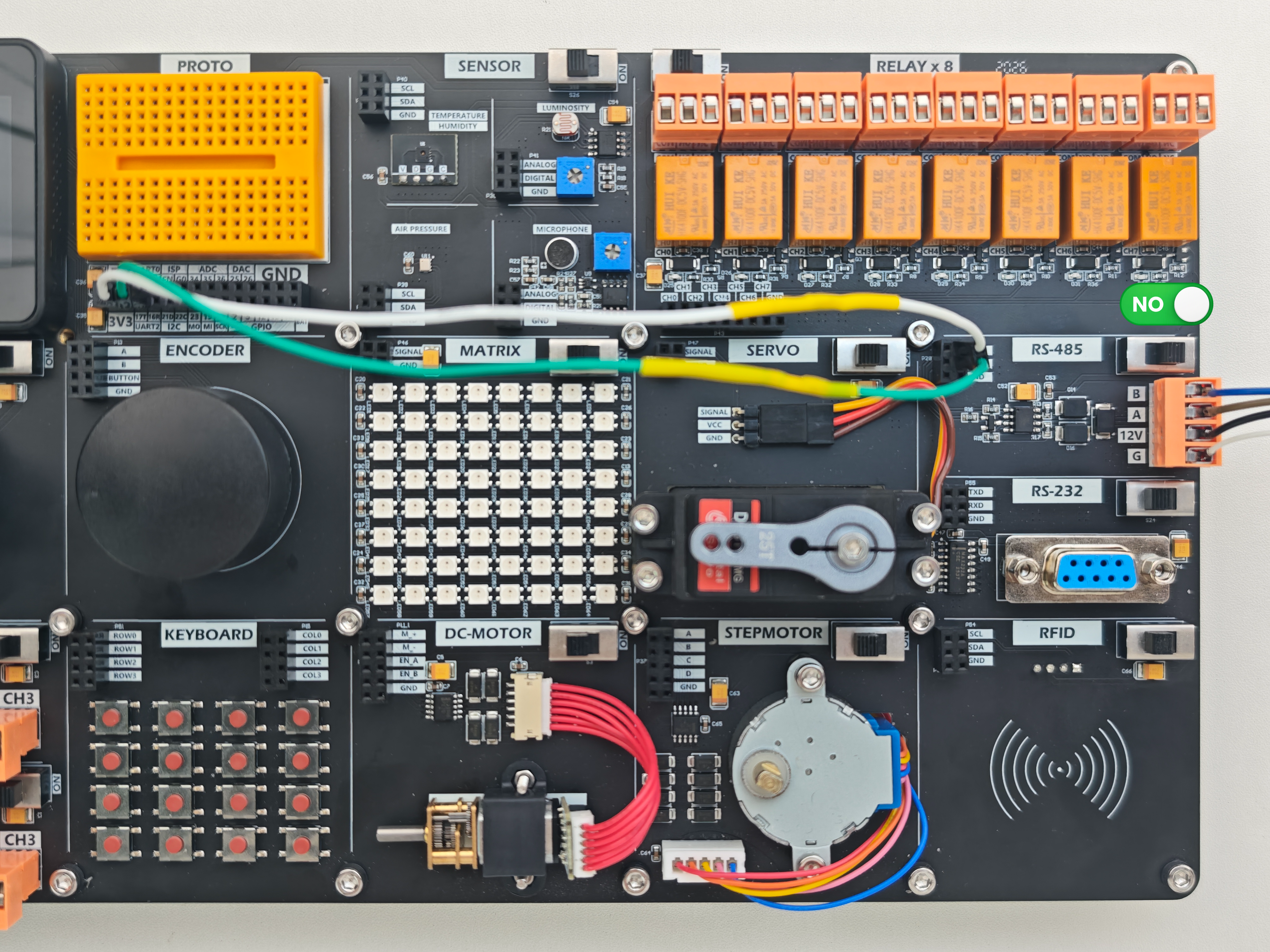
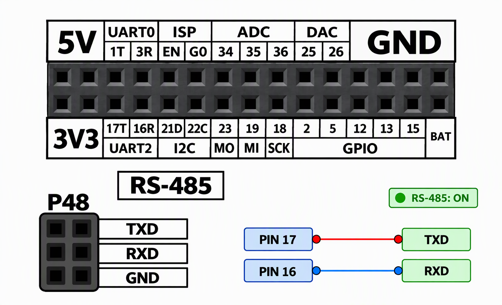
Devices that communicate over a serial port can be connected to the M5Core default serial pins, PIN17 (TXD) and PIN16 (RXD).
Example Program
The program sends an incrementing counter over the half-duplex RS-485 bus once per second, with each message terminated by a newline. The current value is also shown on the LCD.
cpp
1 2 3 4 5 6 7 8 9 10 11 12 13 14 15 16 17 18 19 20 21 22 23 24 25 26 27 28 29 30 31 32 33 34 35 36 37 38 39 40 41 42
#include <M5Unified.h>

constexpr int DIR_PIN = 5;
constexpr uint32_t INTERVAL_MS = 1000;

uint32_t sendValue = 0;
uint32_t lastMs = 0;

void sendAndShow() {
  digitalWrite(DIR_PIN, HIGH);
  delayMicroseconds(10);
  Serial2.printf("%lu\n", sendValue);
  Serial2.flush();
  digitalWrite(DIR_PIN, LOW);

  M5.Lcd.fillRect(0, 55, 320, 150, BLACK);
  M5.Lcd.setCursor(15, 80, 4);
  M5.Lcd.printf("TX:%lu", sendValue++);
}

void setup() {
  M5.begin();
  Serial2.begin(115200, SERIAL_8N1, 16, 17);
  pinMode(DIR_PIN, OUTPUT);
  digitalWrite(DIR_PIN, LOW);

  M5.Lcd.setBrightness(100);
  M5.Lcd.setTextColor(WHITE, BLACK);
  M5.Lcd.fillScreen(BLACK);
  M5.Lcd.setCursor(60, 15, 4);
  M5.Lcd.print("RS485 Auto");

  lastMs = millis();
}

void loop() {
  M5.update();
  if (millis() - lastMs >= INTERVAL_MS) {
    lastMs = millis();
    sendAndShow();
  }
}After uploading the program, you should see the following result.
Page Tools