

Arduino Quick Start
2. Devices & Examples
Demo Board-SHT30
3. M5Unified
4. M5GFX
5. Extensions
Unit
Module
Atomic
Tab5
IoT
Accessories
Luminosity Light Sensor Module
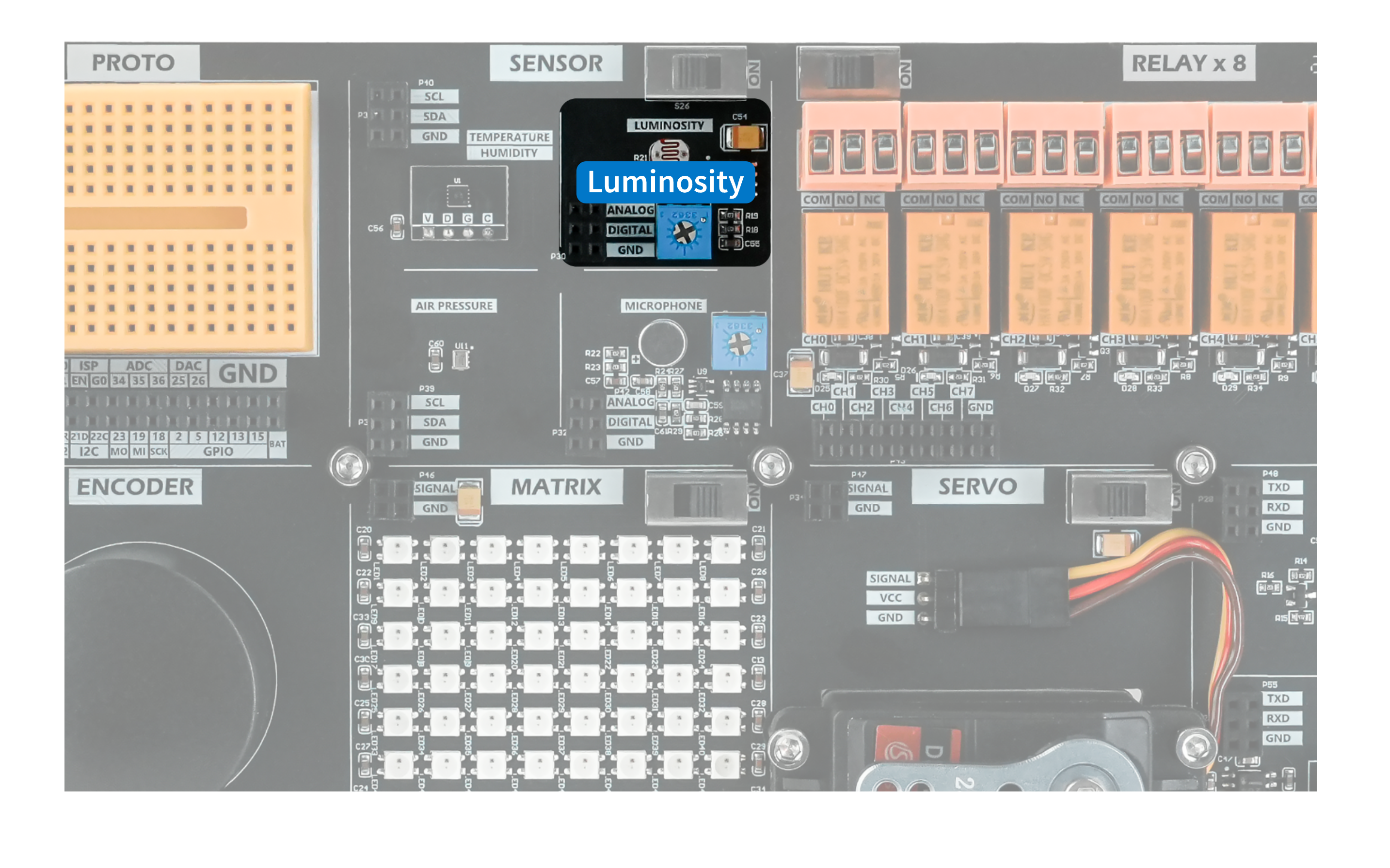
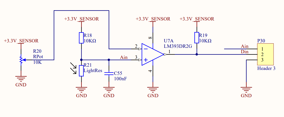
The Light module is a light-sensing module with a photoresistor and an LM393DR2G voltage comparator. It provides an analog voltage output related to changes in illuminance and a digital output for determining whether the light level crosses a configured threshold. An adjustable potentiometer sets the digital output trigger threshold.
Hardware Connection
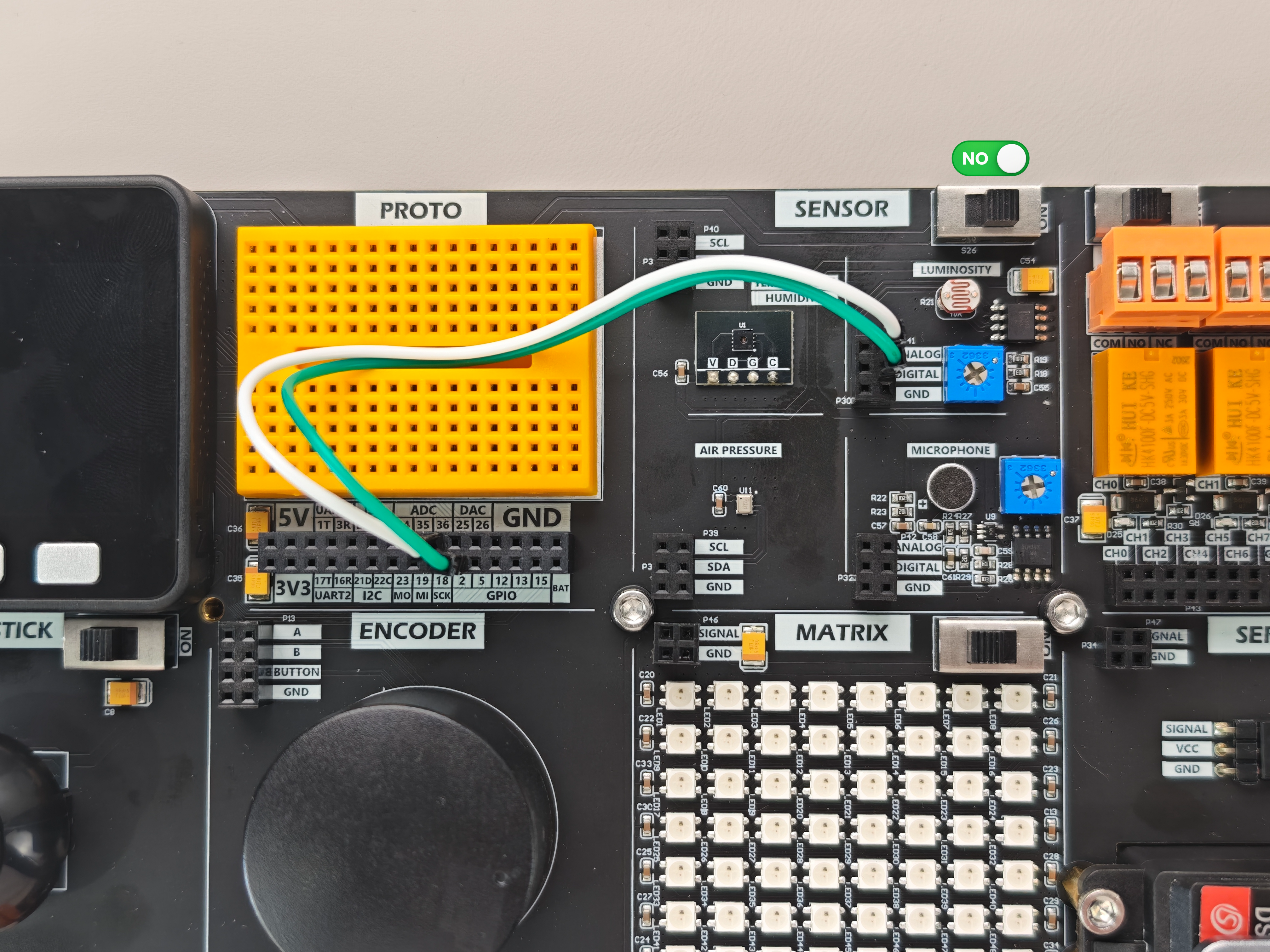
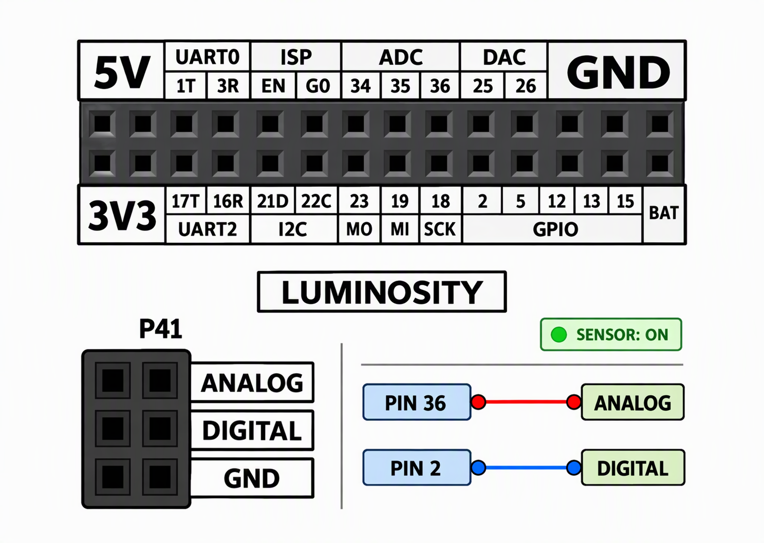
The Light module supports both digital and analog readings. Note that not all GPIO pins on the Basic support ADC conversion. When using analog readings, connect the signal to an ADC-capable pin such as 34, 35, or 36; any general-purpose GPIO can be used for digital readings.
Example Program
This example reads the light sensor's analog and digital outputs and displays the raw ADC value and digital level on the screen and serial monitor.
#include <M5Unified.h>
#include <M5GFX.h>

const int Analog = 36;
const int Digital = 2;
void setup() {
  // put your setup code here, to run once:
  M5.begin();
  pinMode(Digital, INPUT_PULLUP);
  dacWrite(25, 0);
  M5.Lcd.setCursor(100, 0, 4);
  M5.Lcd.print("LUMINOSITY");
}
uint16_t a_data;
uint16_t d_data;
void loop() {
  // put your main code here, to run repeatedly:
  M5.Lcd.clear();
  a_data = analogRead(Analog);
  d_data = digitalRead(Digital);
  Serial.printf("Analog:%0d Digital:%0d\n", a_data, d_data);
  M5.Lcd.setCursor(30, 100, 4);
  M5.Lcd.printf("Analog:%d", a_data);
  M5.Lcd.setCursor(30, 150, 4);
  M5.Lcd.printf("Digital:%d", d_data);
  delay(200);
}After uploading the program, you should see the following result.