

Arduino Quick Start
2. Devices & Examples
Demo Board-SHT30
3. M5Unified
4. M5GFX
5. Extensions
Unit
Module
Atomic
Tab5
IoT
Accessories
StickC IR Transmission
Libraries and example programs related to IR transmission on StickC.
Example Program
Build Requirements
- M5Stack board package version >= 3.3.8
- Board selection = M5StickC
- M5Unified library version >= 0.2.18
- IRremote library version >= 4.7.1
cpp
1 2 3 4 5 6 7 8 9 10 11 12 13 14 15 16 17 18 19 20 21 22 23 24 25 26 27 28 29 30 31 32 33 34 35 36 37 38 39 40 41 42 43 44 45 46 47 48 49 50 51 52 53 54 55 56 57 58 59 60 61 62 63 64 65 66 67 68 69 70 71 72 73 74 75 76 77 78 79 80 81 82 83 84
#include "M5Unified.h"

#define IR_SEND_PIN 9   // Onboard IR transmitter pin. The IR driver circuit is active-low.
#define TX_LED_PIN  10  // Onboard normal LED pin used as the transmission indicator. It is also active-low.

// Invert the IRremote output polarity for active-low IR hardware.
#define USE_ACTIVE_LOW_OUTPUT_FOR_SEND_PIN
// Disable IRremote's built-in feedback LED code because IO10 is controlled manually below.
#define NO_LED_SEND_FEEDBACK_CODE
#include <IRremote.hpp>

constexpr uint8_t LED_ON  = LOW;
constexpr uint8_t LED_OFF = HIGH;
constexpr uint8_t IR_OFF  = HIGH;

uint16_t address = 0x0000;
uint8_t command = 0x55;
uint8_t repeats = 0;

void setup() {
    M5.begin();
    M5.Lcd.setRotation(1);
    M5.Lcd.setFont(&fonts::FreeMonoBold9pt7b);
    M5.Lcd.setTextSize(1);
    M5.Lcd.setTextDatum(top_left);
    M5.Lcd.setTextWrap(false);
    M5.Lcd.setTextColor(TFT_GREEN);

    Serial.begin(115200);
    delay(200);

    // Set idle levels before switching the pins to OUTPUT to avoid unwanted flashes.
    digitalWrite(IR_SEND_PIN, IR_OFF);
    pinMode(IR_SEND_PIN, OUTPUT);

    digitalWrite(TX_LED_PIN, LED_OFF);
    pinMode(TX_LED_PIN, OUTPUT);

    // IR_SEND_PIN is fixed by the macro above, so IRremote 4.x must use begin() without parameters.
    IrSender.begin();

    Serial.println("StickC IRremote active-low example");
    Serial.printf("IR Send Pin: %d\n", IR_SEND_PIN);
    Serial.printf("TX LED Pin : %d\n", TX_LED_PIN);

    M5.Lcd.clear();
    M5.Lcd.setCursor(0, 0);
    M5.Lcd.println("IR Ready");
    M5.Lcd.printf("IR : GPIO%d\n", IR_SEND_PIN);
    M5.Lcd.printf("LED: GPIO%d\n", TX_LED_PIN);

    delay(500);
}

void loop() {
    M5.update();

    M5.Lcd.clear();
    M5.Lcd.setCursor(0, 0);
    M5.Lcd.printf("Send NEC:\n addr=0x%04x\n cmd=0x%02x\n", address, command);

    Serial.printf("Send NEC: addr=0x%04X, cmd=0x%02X, repeats=%u\n",
                  address, command, repeats);

    // Turn on the normal LED only while a transmission is in progress.
    digitalWrite(TX_LED_PIN, LED_ON);

    // Send one NEC frame using the current address and command values.
    IrSender.sendNEC(address, command, repeats);

    // Keep the indicator visible briefly after the short IR frame, then turn it off.
    delay(80);
    digitalWrite(TX_LED_PIN, LED_OFF);

    // Force the active-low IR output back to the inactive level after sending.
    digitalWrite(IR_SEND_PIN, IR_OFF);

    address += 0x0001;
    command += 0x01;
    repeats = 0;

    delay(2000);
}
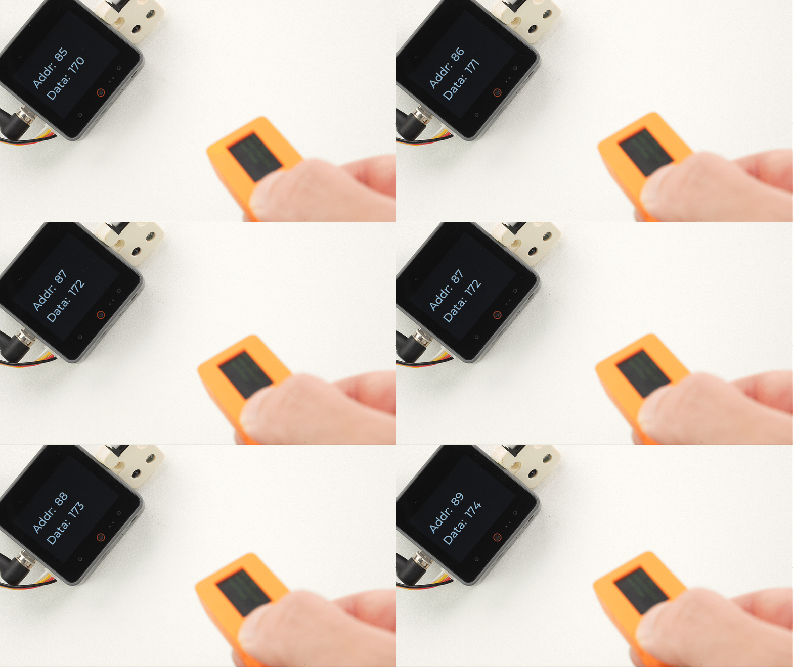
StickC sends a NEC IR signal every two seconds. The address and command start at 0x0000 and 0x55, respectively, and increment with each transmission. An IR receiver supporting the NEC protocol can be used to verify reception.
Page Tools