

Arduino Quick Start
2. Devices & Examples
Demo Board-SHT30
3. M5Unified
4. M5GFX
5. Extensions
Unit
Module
Atomic
Tab5
IoT
Accessories
Servo Module
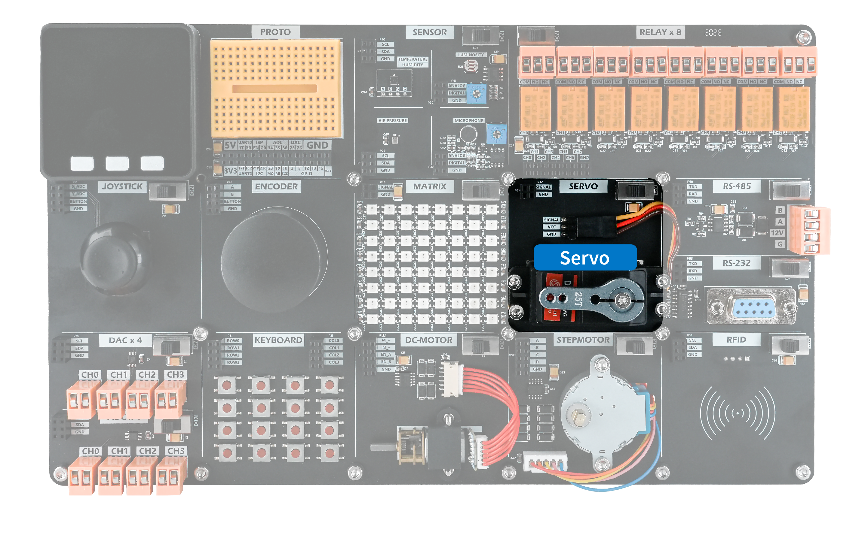
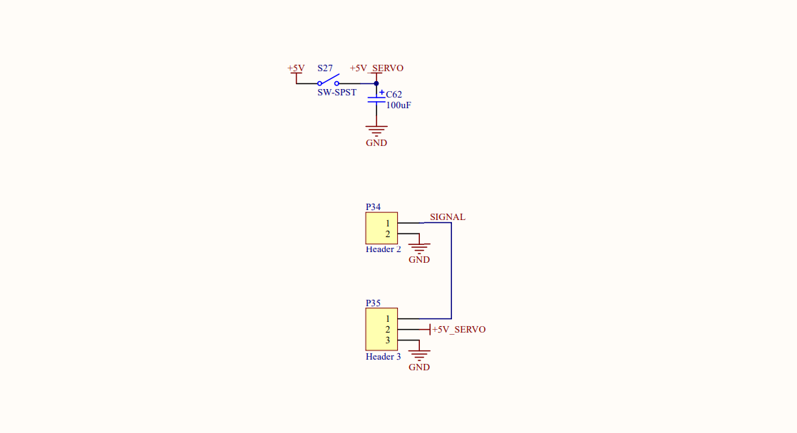
The demo board includes one 0-180 degree servo. The servo is normally powered from an independent 5 V supply and controlled through a single PWM signal line. The control signal runs at 50 Hz with a 20 ms period. A HIGH pulse width of 0.5-2.5 ms corresponds to approximately 0-180 degrees of servo travel, with a duty cycle of approximately 2.5%-12.5%.
Hardware Connection
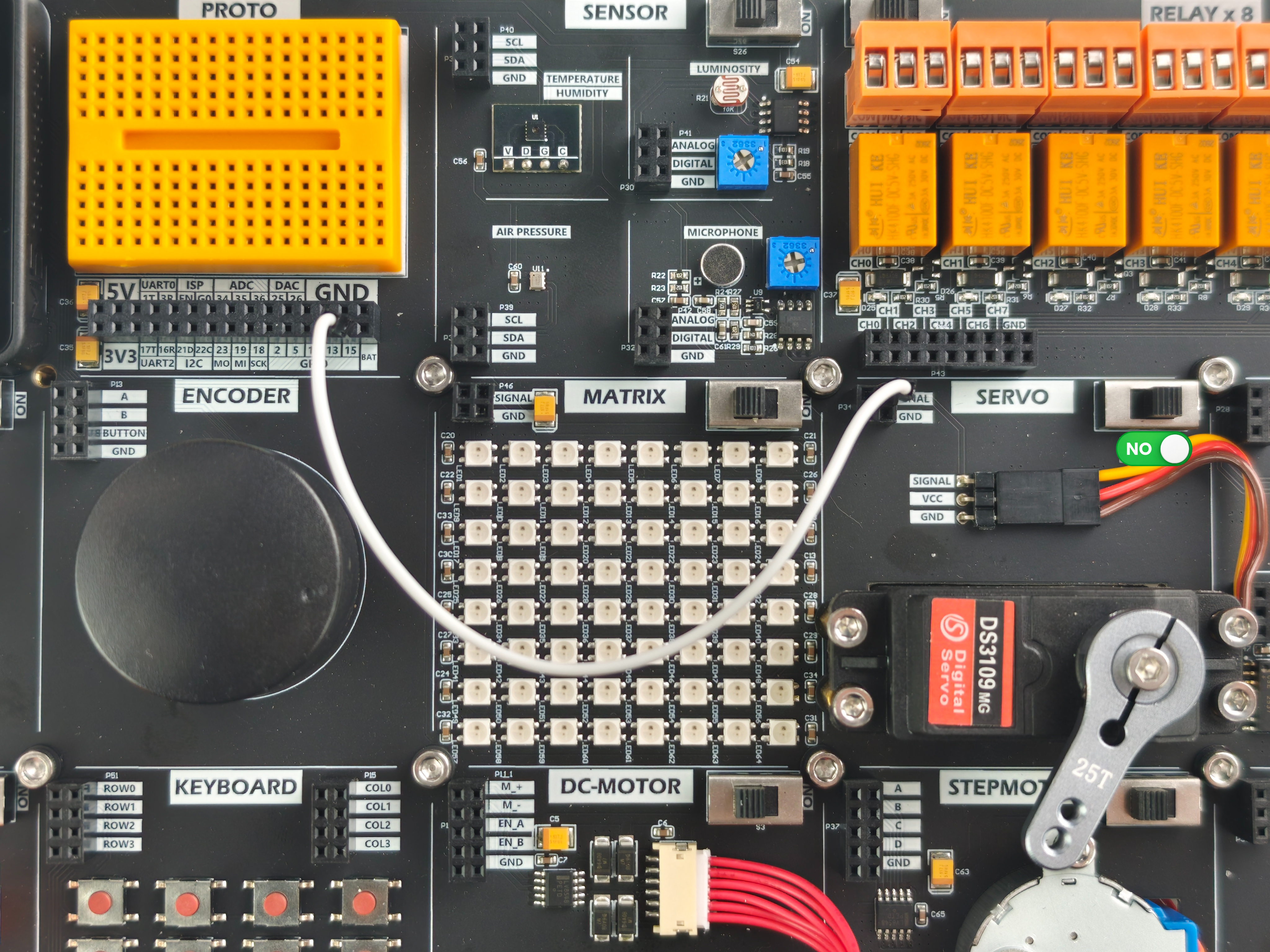
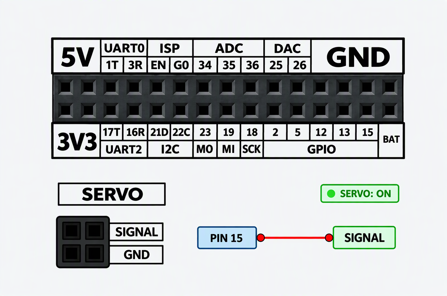
Connect control pin PIN15 to the servo's SIGNAL input and turn on the independent power supply.
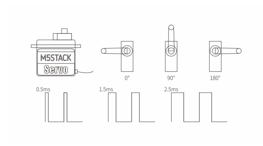
Example Program
This example uses the Arduino-ESP32 3.x LEDC API to rotate the servo to 0, 90, and 180 degrees in sequence.
cpp
1 2 3 4 5 6 7 8 9 10 11 12 13 14 15 16 17 18 19 20 21 22 23 24 25 26 27 28 29 30 31 32 33 34 35 36 37 38 39 40 41 42 43 44 45 46 47 48 49 50 51 52 53 54 55 56 57 58 59 60 61 62 63 64 65 66 67 68
#include <M5Unified.h>

constexpr uint8_t  SERVO_PIN     = 15;
constexpr uint8_t  SERVO_CHANNEL = 0;       // 仅 Arduino-ESP32 2.x 使用
constexpr uint32_t PWM_FREQ_HZ   = 50;
constexpr uint8_t  PWM_RES_BITS  = 14;
constexpr uint32_t PWM_PERIOD_US = 1000000UL / PWM_FREQ_HZ; // 20000 us

bool servoPwmAttach() {
#if defined(ESP_ARDUINO_VERSION_MAJOR) && ESP_ARDUINO_VERSION_MAJOR >= 3
    // Arduino-ESP32 3.x
    return ledcAttach(SERVO_PIN, PWM_FREQ_HZ, PWM_RES_BITS);
#else
    // Arduino-ESP32 2.x
    ledcSetup(SERVO_CHANNEL, PWM_FREQ_HZ, PWM_RES_BITS);
    ledcAttachPin(SERVO_PIN, SERVO_CHANNEL);
    return true;
#endif
}

void servoWriteDuty(uint32_t duty) {
#if defined(ESP_ARDUINO_VERSION_MAJOR) && ESP_ARDUINO_VERSION_MAJOR >= 3

    ledcWrite(SERVO_PIN, duty);
#else

    ledcWrite(SERVO_CHANNEL, duty);
#endif
}

void servoWriteAngle(uint8_t angle) {
    if (angle > 180) {
        return;
    }

    const uint32_t pulse_us = 500UL + 2000UL * angle / 180UL;

    const uint32_t duty =
        (pulse_us * (1UL << PWM_RES_BITS) + PWM_PERIOD_US / 2) /
        PWM_PERIOD_US;

    servoWriteDuty(duty);
}

void setup() {
    M5.begin();

    M5.Lcd.setCursor(120, 110, 4);
    M5.Lcd.println("SERVO");

    if (!servoPwmAttach()) {
        M5.Lcd.println("LEDC init failed");
        while (true) {
            delay(1000);
        }
    }
}

void loop() {
    servoWriteAngle(0);   // 0°
    delay(1000);

    servoWriteAngle(90);  // 90°
    delay(1000);

    servoWriteAngle(180); // 180°
    delay(1000);
}After uploading the program, you should see the following result.
Page Tools