

Arduino Quick Start
2. Devices & Examples
Demo Board-SHT30
3. M5Unified
4. M5GFX
5. Extensions
Unit
Module
Atomic
Tab5
IoT
Accessories
Joystick Input Module
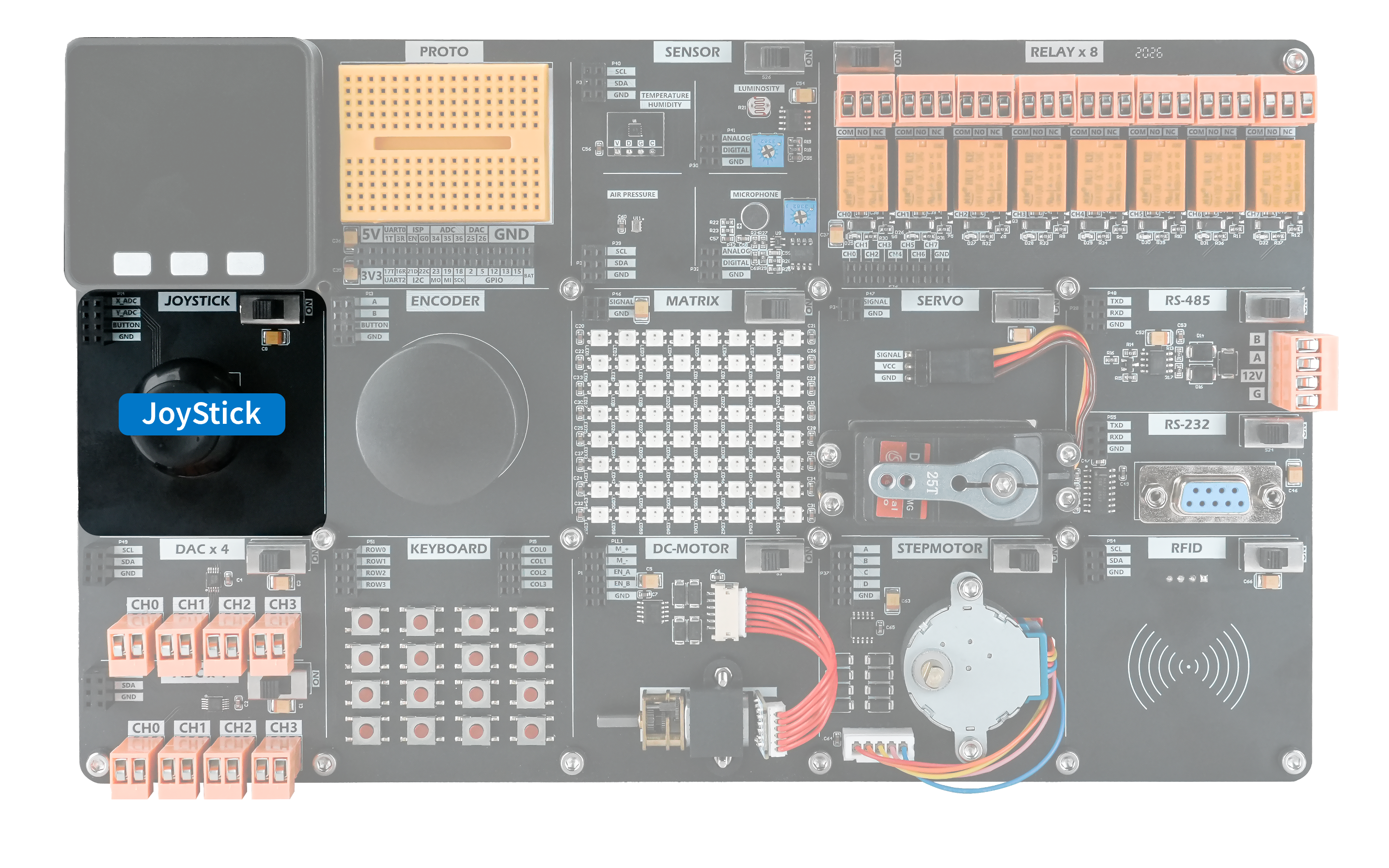
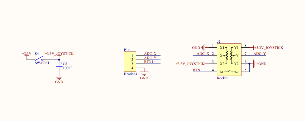
The Joystick is an input module with two potentiometers and a pushbutton switch. As the joystick moves, the divided outputs of the two potentiometers change with its position. Connect X_ADC and Y_ADC to ADC-capable pins on the host to read their raw ADC values. When the joystick is pressed, the internal switch closes and the BUTTON pin goes LOW; when released, it returns HIGH through a pull-up resistor.
Hardware Connection
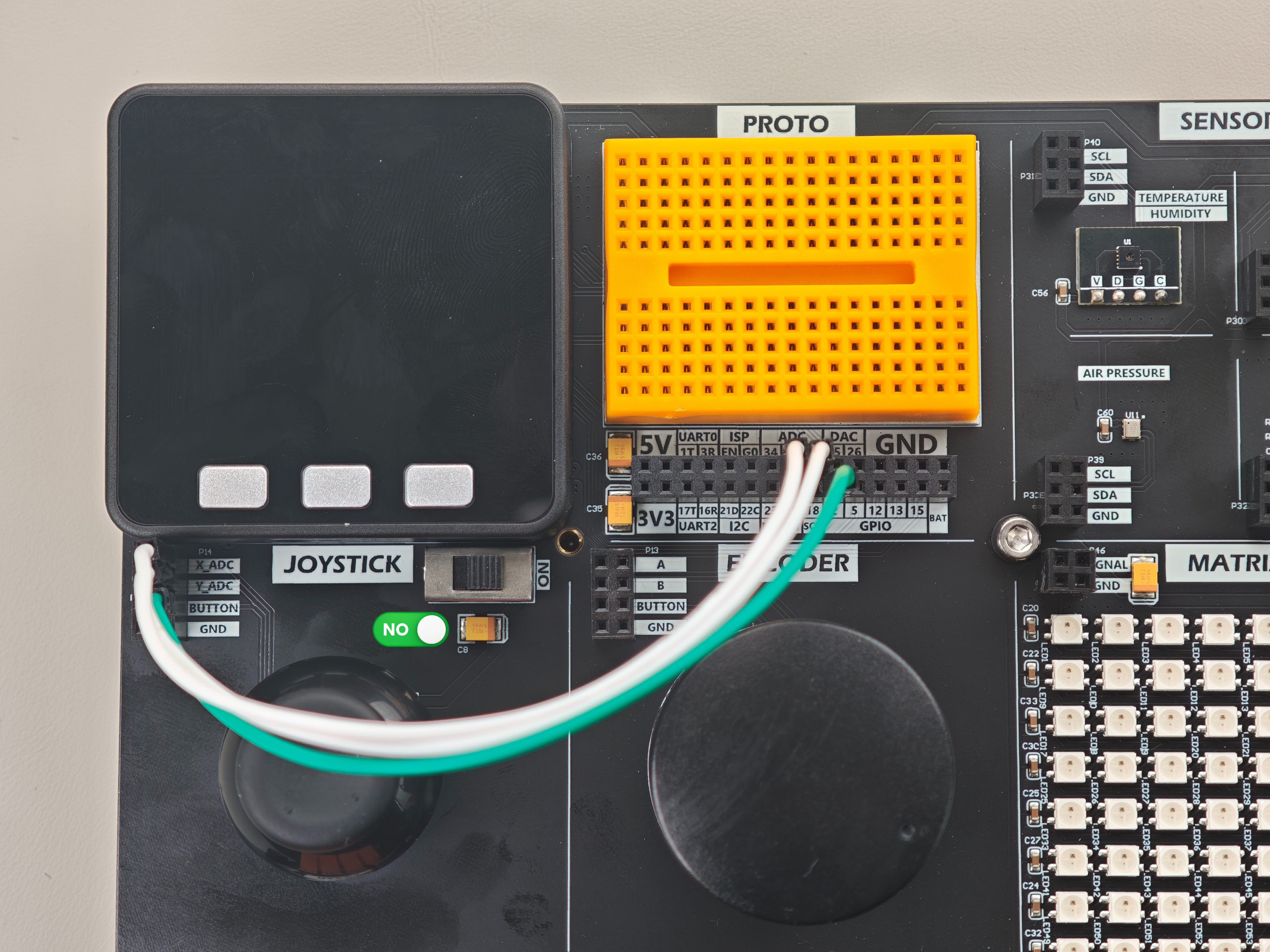
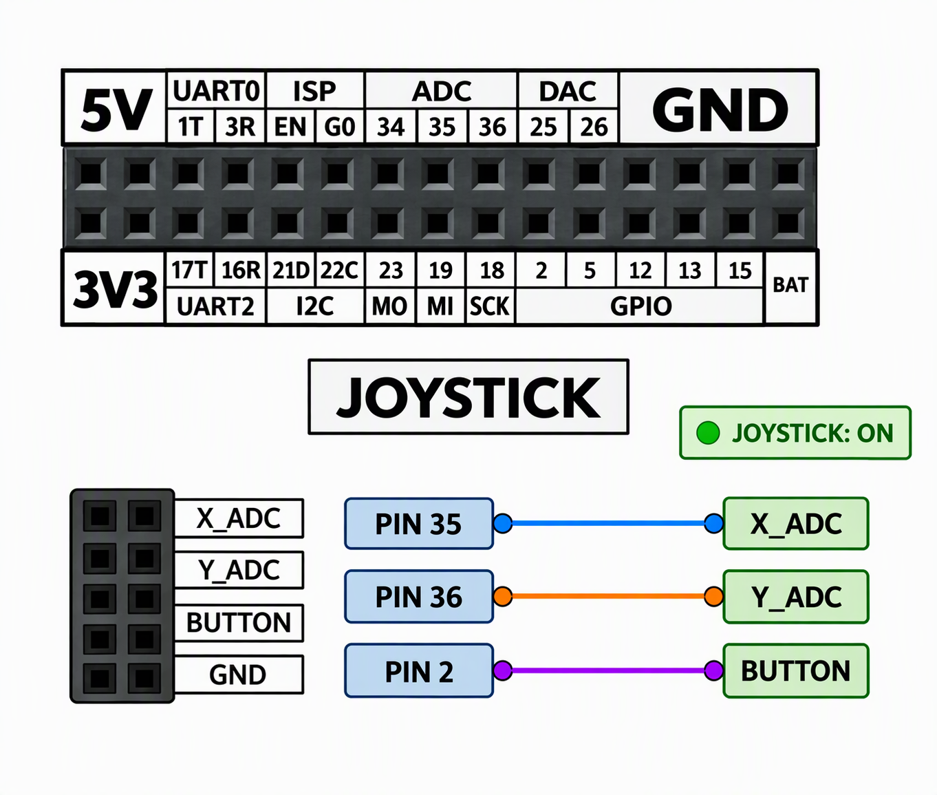
Connect the Joystick module's X_ADC and Y_ADC outputs to ADC-capable pins on the Basic (this example uses PIN35 and PIN36), and connect BUTTON to PIN2.
Example Program
This example reads the joystick position and button state and displays them on the screen and serial monitor.
#include "M5Unified.h"
#include <M5GFX.h>

void setup() {
  M5.begin();
  pinMode(2, INPUT_PULLUP);

  pinMode(35, INPUT);
  pinMode(36, INPUT);
  dacWrite(25, 0);
  M5.Lcd.setCursor(100, 0, 4);
  M5.Lcd.print("JOYSTICK");
}
uint16_t x_data;
uint16_t y_data;
uint8_t button_data;
void loop() {
  // put your main code here, to run repeatedly:
  x_data = analogRead(35);
  y_data = analogRead(36);
  button_data = digitalRead(2);
  Serial.printf("x:%0d y:%0d button:%d\n", x_data, y_data, button_data);

  M5.Lcd.setCursor(0, 120, 4);
  M5.Lcd.printf("X:%04d   Y:%04d\n", x_data, y_data);
  M5.Lcd.printf("Button:%d\n", button_data);
  delay(200);
}After uploading the program, you should see the following result.