

Arduino入門
2. デバイス&サンプル
3. M5Unified
4. M5GFX
5. 拡張モジュール&サンプル
Unit
Module
Atomic
Tab5
IoT
アクセサリー
Unit 2Relay Arduino チュートリアル
1. 準備
- 環境設定: Arduino IDE はじめにガイド を参照して IDE のインストールを完了し、使用する開発ボードに対応するボードマネージャとドライバライブラリをインストールしてください。
- 使用するライブラリ:
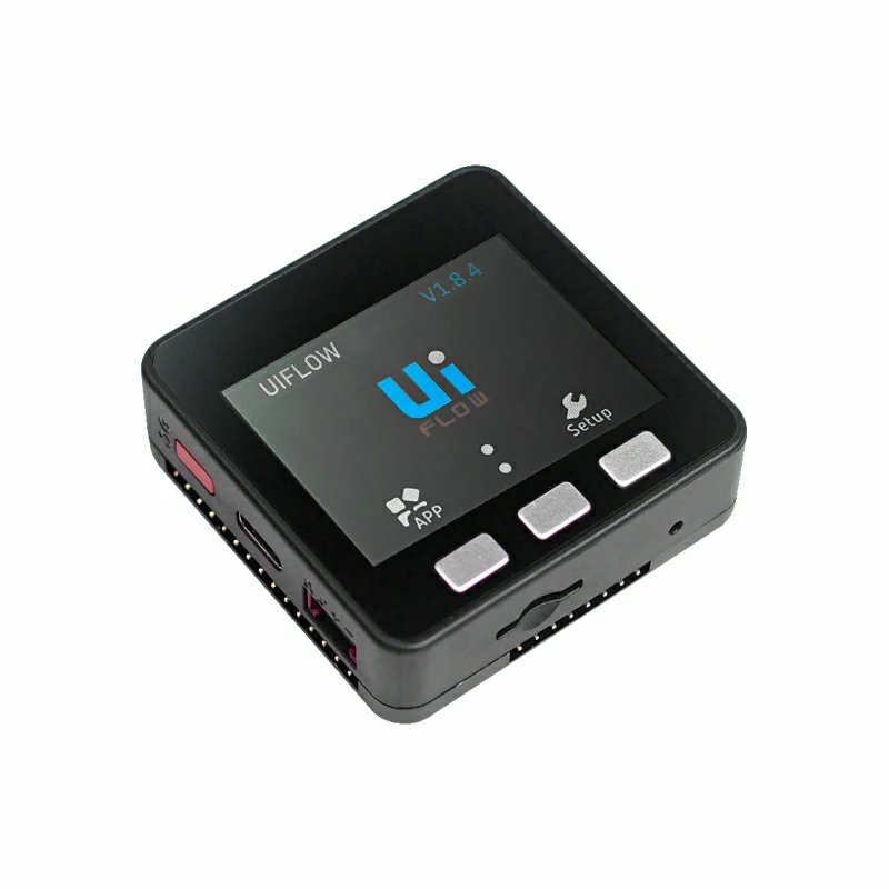
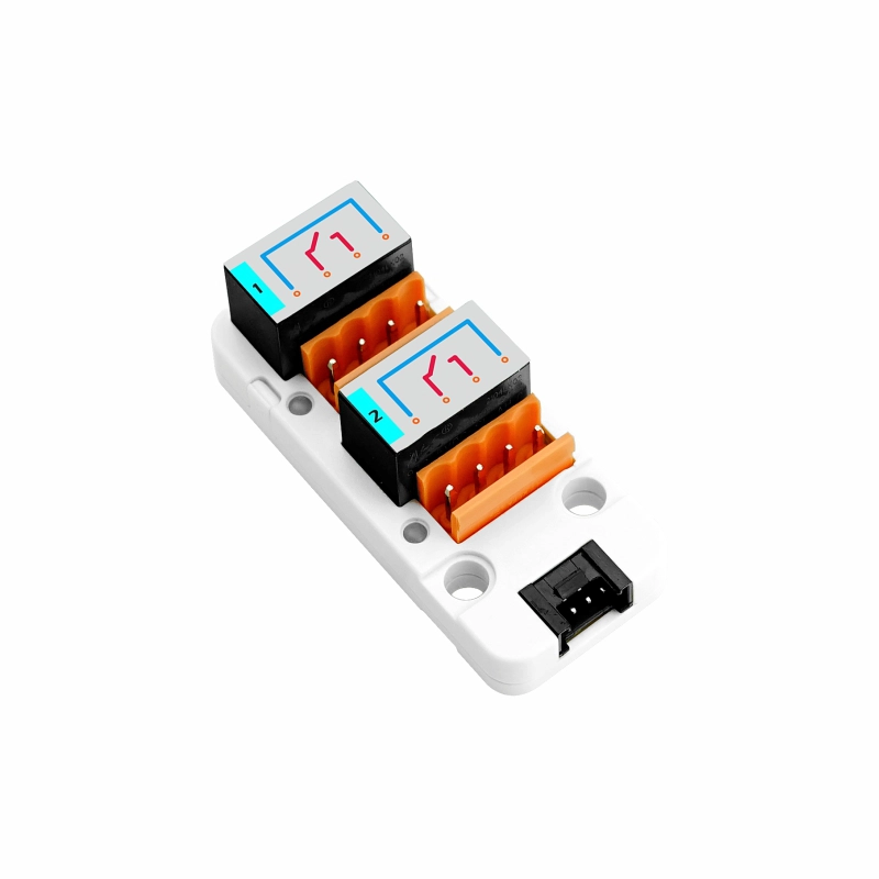
- 使用するハードウェア:
2. 注意事項
ピン互換性
ホストごとにピン構成が異なるため、M5Stack ではユーザーが簡単に確認できるよう、公式のピン互換性表を提供しています。実際のピン接続に応じてサンプルプログラムを変更してください。
3. サンプルプログラム
- このチュートリアルでは Basic V2.7 と Unit 2Relay を組み合わせ、モジュールを Port A に接続します。Unit 2Relay は GPIO の HIGH/LOW レベルで直接制御します。RELAY-1 は Basic V2.7 の
G22、RELAY-2 はG21に対応します。出力が HIGH のとき対応するリレーが通電し、状態表示 LED が点灯します。出力が LOW のときリレーは解放されます。
cpp
1 2 3 4 5 6 7 8 9 10 11 12 13 14 15 16 17 18 19 20 21 22 23 24 25 26 27 28 29 30 31 32 33 34 35 36 37 38 39 40 41 42 43 44 45 46 47 48 49 50 51 52 53 54 55 56 57 58 59 60 61 62 63 64 65 66 67 68 69 70 71 72 73 74 75 76 77 78 79 80 81 82 83 84 85 86 87 88 89 90 91 92 93 94 95 96 97 98 99 100 101 102 103 104 105 106 107 108 109 110 111 112 113 114 115 116 117 118 119 120 121 122 123 124 125 126 127 128 129 130 131 132 133 134 135 136 137 138 139 140 141 142 143 144 145 146 147 148 149 150 151 152 153 154 155 156 157 158 159 160 161 162 163 164 165 166 167 168 169 170 171 172
#include <M5Unified.h>

namespace {
constexpr uint16_t COLOR_BG      = 0x1082;
constexpr uint16_t COLOR_SURFACE = 0x2104;
constexpr uint16_t COLOR_HEADER  = 0x0349;
constexpr uint16_t COLOR_BORDER  = 0x52AA;
constexpr uint16_t COLOR_MUTED   = 0xBDF7;
constexpr uint16_t COLOR_GREEN   = 0x2E8B;
constexpr uint16_t COLOR_RED     = 0xD249;

constexpr int16_t CHANNEL_Y       = 148;
constexpr int16_t CHANNEL_WIDTH   = 100;
constexpr int16_t CHANNEL_HEIGHT  = 43;
constexpr int16_t CHANNEL_GAP     = 20;
constexpr int16_t CHANNEL_START_X = 50;

int relayPins[2]   = {-1, -1};
bool relayState[2] = {false, false};
uint8_t stepIndex  = 0;

void drawControlStatus()
{
    M5.Display.fillRect(0, 38, 320, 36, COLOR_BG);
    M5.Display.setFont(&fonts::Font2);
    M5.Display.setTextDatum(textdatum_t::middle_left);
    M5.Display.setTextColor(COLOR_MUTED, COLOR_BG);
    M5.Display.drawString("CONTROL", 12, 56);
    M5.Display.drawString("CHANNELS", 174, 56);

    M5.Display.fillRoundRect(82, 44, 70, 25, 4, COLOR_GREEN);
    M5.Display.fillRoundRect(258, 44, 50, 25, 4, COLOR_SURFACE);
    M5.Display.drawRoundRect(258, 44, 50, 25, 4, COLOR_BORDER);

    M5.Display.setTextDatum(textdatum_t::middle_center);
    M5.Display.setTextColor(TFT_BLACK, COLOR_GREEN);
    M5.Display.drawString("GPIO", 117, 56);
    M5.Display.setTextColor(TFT_WHITE, COLOR_SURFACE);
    M5.Display.drawString("2", 283, 56);
}

void drawAction(const char *message)
{
    M5.Display.fillRoundRect(10, 81, 300, 38, 4, COLOR_SURFACE);
    M5.Display.drawRoundRect(10, 81, 300, 38, 4, COLOR_BORDER);
    M5.Display.setFont(&fonts::Font2);
    M5.Display.setTextDatum(textdatum_t::middle_left);
    M5.Display.setTextColor(COLOR_MUTED, COLOR_SURFACE);
    M5.Display.drawString("LAST ACTION", 20, 100);
    M5.Display.setTextColor(TFT_WHITE, COLOR_SURFACE);
    M5.Display.drawString(message, 119, 100);
}

void drawChannel(uint8_t channel)
{
    const bool isOn      = relayState[channel];
    const uint16_t color = isOn ? COLOR_GREEN : COLOR_BORDER;
    const int16_t x = CHANNEL_START_X + channel * (CHANNEL_WIDTH + CHANNEL_GAP);
    char channelLabel[5] = {};
    snprintf(channelLabel, sizeof(channelLabel), "CH%u",
             static_cast<unsigned>(channel + 1));

    M5.Display.fillRoundRect(x, CHANNEL_Y, CHANNEL_WIDTH, CHANNEL_HEIGHT, 4,
                             COLOR_SURFACE);
    M5.Display.drawRoundRect(x, CHANNEL_Y, CHANNEL_WIDTH, CHANNEL_HEIGHT, 4,
                             color);
    M5.Display.setTextDatum(textdatum_t::middle_center);
    M5.Display.setFont(&fonts::Font2);
    M5.Display.setTextColor(COLOR_MUTED, COLOR_SURFACE);
    M5.Display.drawString(channelLabel, x + CHANNEL_WIDTH / 2, CHANNEL_Y + 12);
    M5.Display.setTextColor(isOn ? COLOR_GREEN : TFT_WHITE, COLOR_SURFACE);
    M5.Display.drawString(isOn ? "ON" : "OFF", x + CHANNEL_WIDTH / 2,
                          CHANNEL_Y + 31);
}

void drawAllChannels()
{
    M5.Display.fillRect(0, 125, 320, 22, COLOR_BG);
    M5.Display.setFont(&fonts::Font2);
    M5.Display.setTextDatum(textdatum_t::middle_left);
    M5.Display.setTextColor(COLOR_MUTED, COLOR_BG);
    M5.Display.drawString("RELAY STATUS", 10, 136);

    for (uint8_t channel = 0; channel < 2; ++channel) {
        drawChannel(channel);
    }
}

void drawButtonHint(int16_t x, char button, const char *label, uint16_t color)
{
    char buttonLabel[2] = {button, '\0'};

    M5.Display.fillCircle(x, 220, 11, color);
    M5.Display.setFont(&fonts::Font2);
    M5.Display.setTextDatum(textdatum_t::middle_center);
    M5.Display.setTextColor(TFT_BLACK, color);
    M5.Display.drawString(buttonLabel, x, 220);
    M5.Display.setTextDatum(textdatum_t::middle_left);
    M5.Display.setTextColor(TFT_WHITE, COLOR_SURFACE);
    M5.Display.drawString(label, x + 16, 220);
}

void drawMainUi()
{
    M5.Display.fillScreen(COLOR_BG);
    M5.Display.fillRect(0, 0, 320, 34, COLOR_HEADER);
    M5.Display.setFont(&fonts::Font4);
    M5.Display.setTextDatum(textdatum_t::middle_center);
    M5.Display.setTextColor(TFT_WHITE, COLOR_HEADER);
    M5.Display.drawString("UNIT 2RELAY", 160, 17);

    drawControlStatus();
    drawAction("Ready");
    drawAllChannels();

    M5.Display.fillRect(0, 202, 320, 38, COLOR_SURFACE);
    M5.Display.drawFastHLine(0, 202, 320, COLOR_BORDER);
    drawButtonHint(48, 'A', "STEP", COLOR_GREEN);
    drawButtonHint(210, 'C', "ALL", COLOR_RED);
}

void writeRelay(uint8_t channel, bool state)
{
    digitalWrite(relayPins[channel], state ? HIGH : LOW);
    relayState[channel] = state;
}
}  // namespace

void setup()
{
    M5.begin();
    Serial.begin(115200);
    M5.Display.setRotation(1);

    // Grove Port A: white wire controls RELAY-1, yellow wire controls RELAY-2.
    relayPins[0] = M5.getPin(m5::pin_name_t::port_a_pin2);
    relayPins[1] = M5.getPin(m5::pin_name_t::port_a_pin1);
    for (uint8_t channel = 0; channel < 2; ++channel) {
        pinMode(relayPins[channel], OUTPUT);
        writeRelay(channel, false);
    }

    drawMainUi();
}

void loop()
{
    M5.update();

    if (M5.BtnA.wasPressed()) {
        const uint8_t channel = stepIndex % 2;
        const bool state      = stepIndex < 2;
        char message[20]      = {};

        writeRelay(channel, state);
        snprintf(message, sizeof(message), "Relay %u  %s",
                 static_cast<unsigned>(channel + 1), state ? "ON" : "OFF");
        drawAction(message);
        drawChannel(channel);
        stepIndex = (stepIndex + 1) % 4;
    }

    if (M5.BtnC.wasPressed()) {
        const bool state = !(relayState[0] && relayState[1]);
        for (uint8_t channel = 0; channel < 2; ++channel) {
            writeRelay(channel, state);
        }

        drawAction(state ? "All channels ON" : "All channels OFF");
        drawAllChannels();
    }
}4. コンパイルとアップロード
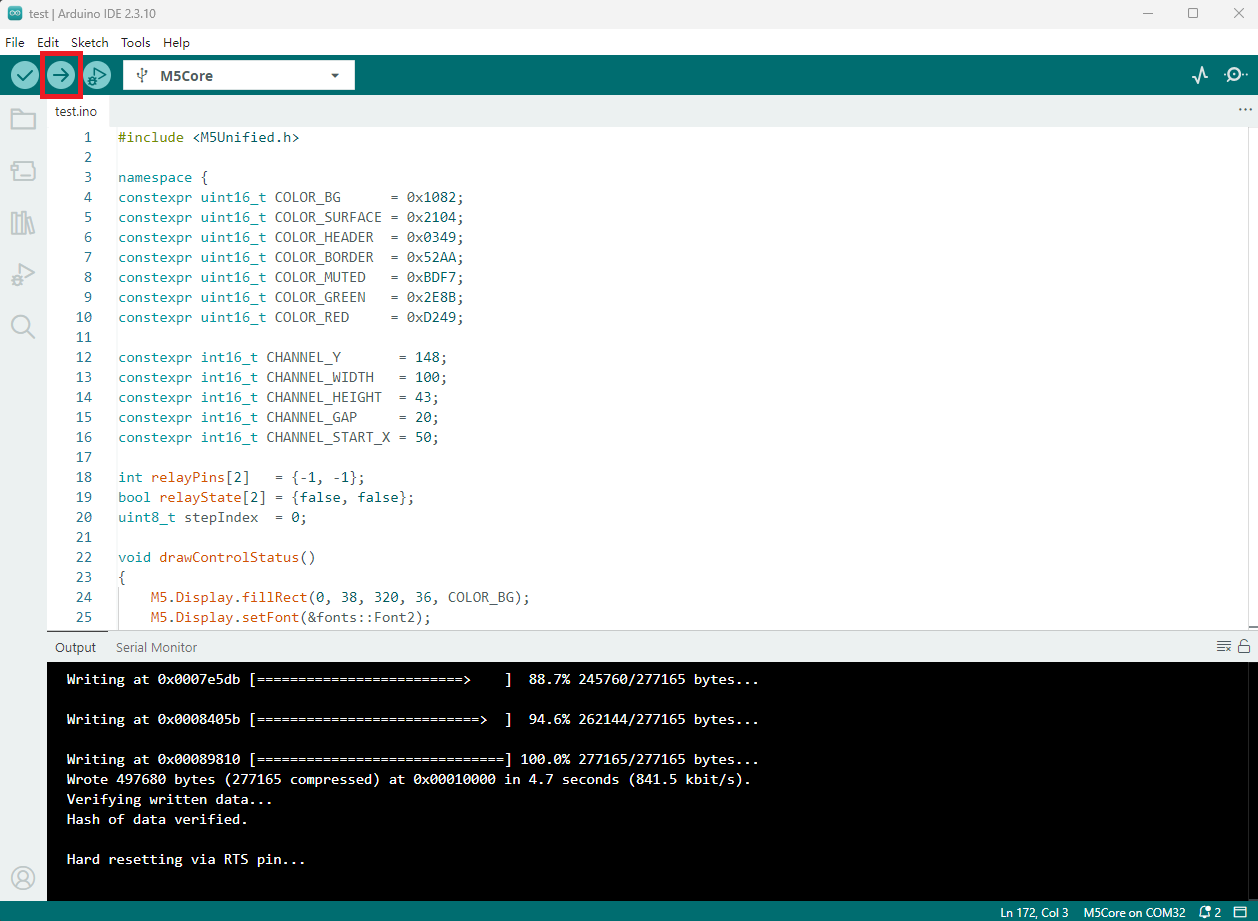
- 上記のサンプルコードをプロジェクトのコード欄にコピーして貼り付け、デバイスポートを選択します(詳細は プログラムのコンパイルと書き込み を参照してください)。Arduino IDE の左上にあるコンパイル&アップロードボタンをクリックし、プログラムのコンパイルとデバイスへのアップロードが完了するまで待ちます。
5. リレー制御
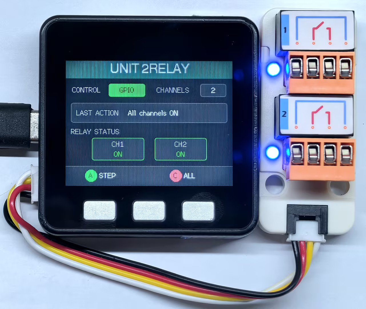
- ボタン A を押すと、2 つのリレーが
CH1 ON → CH2 ON → CH1 OFF → CH2 OFFの順に切り替わります。ボタン C を押すと、現在 2 系統すべてが ON でなければすべてのリレーを ON にし、すでに両方が ON であればすべてのリレーを OFF にします。画面のCH1、CH2の状態ブロックとLAST ACTIONの領域には、現在の制御結果が反映されます。
Page Tools