

Arduino入門
2. デバイス&サンプル
3. M5Unified
4. M5GFX
5. 拡張モジュール&サンプル
Unit
Module
Atomic
Tab5
IoT
アクセサリー
Unit Color Arduino チュートリアル
1. 準備
- 環境設定:Arduino IDE 入門チュートリアルを参照して IDE をインストールし、使用する開発ボードに対応したボードマネージャーと必要なドライバライブラリをインストールします。
- 使用するドライバライブラリ:
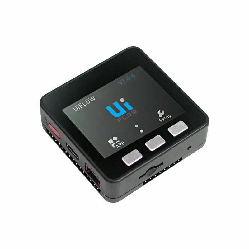
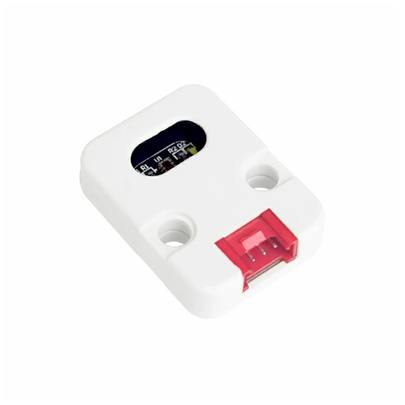
- 使用するハードウェア製品:
2. 注意事項
ピン互換性
ホストデバイスごとにピン構成が異なります。M5Stack 公式のピン互換性表を確認し、実際のピン接続に合わせてサンプルプログラムを変更してください。
3. サンプルプログラム
- 本チュートリアルでは、Basic V2.7 と Unit Color を使用します。Unit Color は I2C 通信を使用し、デフォルトアドレスは
0x29です。接続後に使用するピンはG21 (SDA)とG22 (SCL)です。
cpp
1 2 3 4 5 6 7 8 9 10 11 12 13 14 15 16 17 18 19 20 21 22 23 24 25 26 27 28 29 30 31 32 33 34 35 36 37 38 39 40 41 42 43 44 45 46 47 48 49 50 51 52 53 54 55 56 57 58 59 60 61 62 63 64 65 66 67 68 69 70 71 72 73
#include <M5Unified.h>
#include <M5GFX.h>
#include "Adafruit_TCS34725.h"

#define commonAnode  true  // set to false if using a common cathode LED.

byte gammatable[256];  // our RGB -> eye-recognized gamma color

static uint16_t color16(uint16_t r, uint16_t g, uint16_t b)
{
    uint16_t _color;
    _color = (uint16_t)(r & 0xF8) << 8;
    _color |= (uint16_t)(g & 0xFC) << 3;
    _color |= (uint16_t)(b & 0xF8) >> 3;
    return _color;
}

Adafruit_TCS34725 tcs = Adafruit_TCS34725(TCS34725_INTEGRATIONTIME_50MS, TCS34725_GAIN_4X);

void setup()
{
    M5.begin();
    M5.Power.begin();
    M5.Lcd.setTextSize(2);
    Serial.println("Color View Test!");
    while (!tcs.begin(TCS34725_ADDRESS, &Wire)) { //PORT.A
        Serial.println("No TCS34725 found ... check your connections");
        M5.Lcd.drawString("No Found sensor.", 50, 100, 4);
        delay(1000);
    }
    tcs.setIntegrationTime(TCS34725_INTEGRATIONTIME_154MS);  // Sets the integration time for the
    tcs.setGain(TCS34725_GAIN_4X);                           // Adjusts the gain on the TCS34725
}

void loop()
{
    uint16_t clear, red, green, blue;
    tcs.getRawData(&red, &green, &blue,
                   &clear);  // Reads the raw red, green, blue and clear channel
                             // values

    // Figure out some basic hex code for visualization.  生成对应的十六进制代码
    uint32_t sum = clear;
    float r, g, b;
    r = red;
    r /= sum;
    g = green;
    g /= sum;
    b = blue;
    b /= sum;
    r *= 256;
    g *= 256;
    b *= 256;
    uint16_t _color = color16((int)r, (int)g, (int)b);

    M5.Lcd.setCursor(0, 20);                 // Place the cursor at (0,20)
    M5.Lcd.fillRect(0, 20, 120, 80, BLACK);  // Fill the screen with a black rectangle

    M5.Lcd.print("C:");
    M5.Lcd.println(clear);
    M5.Lcd.print("R:");
    M5.Lcd.println(red);
    M5.Lcd.print("G:");
    M5.Lcd.println(green);
    M5.Lcd.print("B:");
    M5.Lcd.println(blue);
    M5.Lcd.print("0x");
    M5.Lcd.print((int)r, HEX);
    M5.Lcd.print((int)g, HEX);
    M5.Lcd.print((int)b, HEX);

    delay(1000);
}4. コンパイルとアップロード
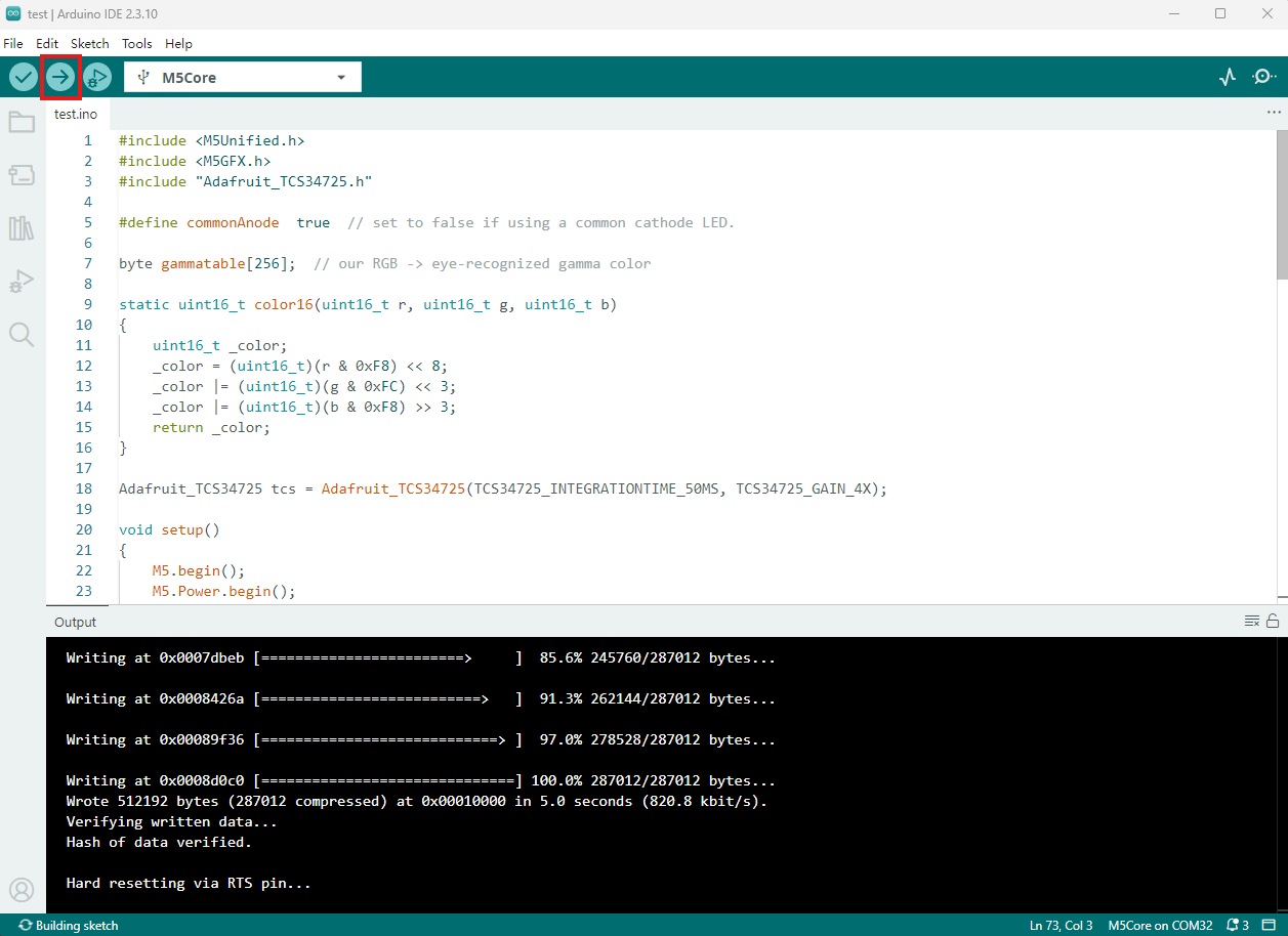
- 上記のサンプルコードをプロジェクトのコード領域に貼り付け、デバイスポートを選択します。詳細はプログラムのコンパイルと書き込みを参照してください。Arduino IDE 左上のコンパイルおよびアップロードボタンをクリックし、プログラムのコンパイルとデバイスへのアップロードが完了するまで待ちます。
5. 色認識
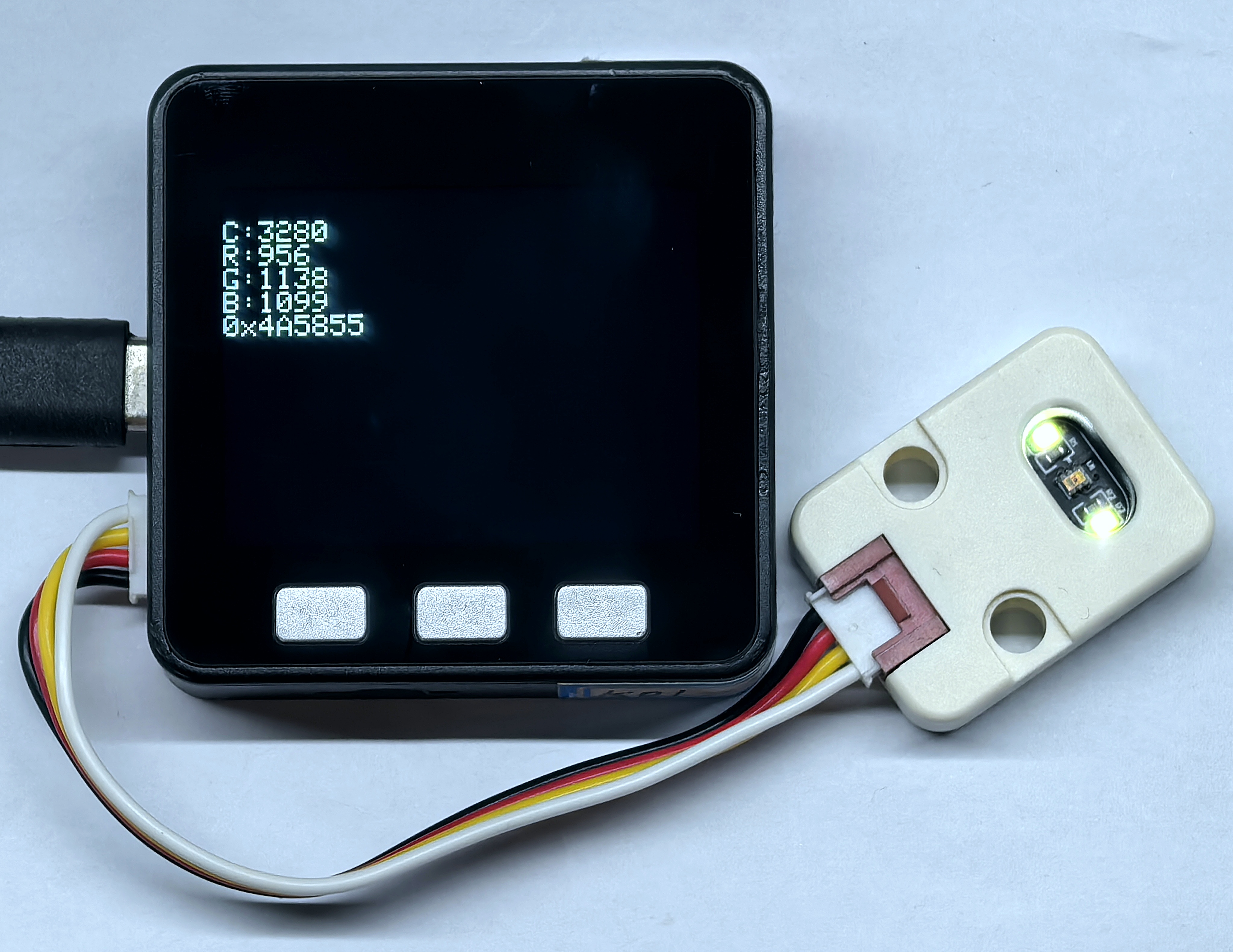
- プログラムの実行後、画面は 1 秒ごとに更新され、Unit Color が取得したクリア、赤、緑、青の各チャンネルの生データと、変換後の RGB 16 進数データが表示されます。
Page Tools